Inductance measurement circuit
An inductance measurement and circuit technology, applied in the field of measurement circuits, can solve the problems of difficulty in popularization, high price, and large measurement errors, and achieve the effects of simple circuit structure, high measurement accuracy, and simple operation.
- Summary
- Abstract
- Description
- Claims
- Application Information
AI Technical Summary
Problems solved by technology
Method used
Image
Examples
Embodiment Construction
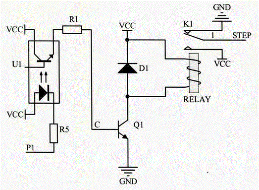
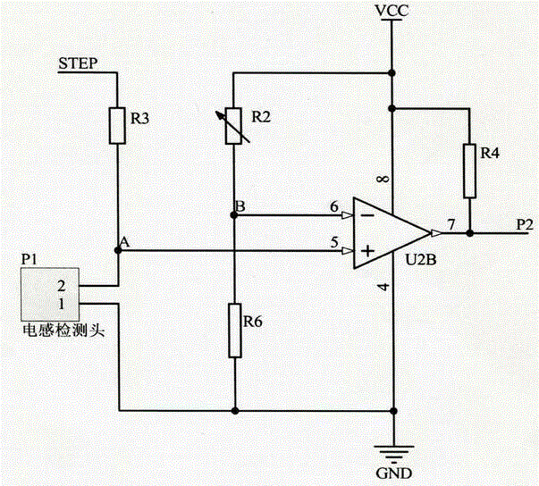
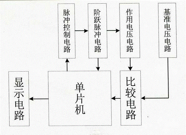
[0007] This technical scheme is made of pulse control circuit 1, step pulse circuit 2, action voltage circuit 3, reference voltage circuit 4, display circuit 5, single-chip microcomputer 6, and comparison circuit 7, (as image 3 Shown) described pulse control circuit 1 is connected with the input end of step pulse circuit 2 and the output end of single-chip microcomputer 6 respectively, and the output end of described step pulse circuit 2 is connected with the input end of action voltage circuit 3 and single-chip microcomputer 6 respectively connected, the output end of the action voltage circuit 3 is connected with the input end of the comparison circuit 7, the output end of the reference voltage circuit 4 is connected with the input end of the comparison circuit 7, and the output end of the comparison circuit 7 is connected with the single chip microcomputer 6 The input end of the single chip microcomputer 6 is connected with the input end of the display circuit 5 to form an ...
PUM
 Abstract
Description
Claims
Application Information
 - R&D Engineer
- R&D Manager
- IP Professional
- Industry Leading Data Capabilities
- Powerful AI technology
- Patent DNA Extraction
Browse by: Latest US Patents, China's latest patents, Technical Efficacy Thesaurus, Application Domain, Technology Topic, Popular Technical Reports.
© 2024 PatSnap. All rights reserved.Legal|Privacy policy|Modern Slavery Act Transparency Statement|Sitemap|About US| Contact US: help@patsnap.com


