Rotary magnetic device

A rotary type, magnetic technology, applied to the power devices, electromechanical devices, electrical components and other directions inside the switch, can solve problems such as difficulty and complex structure, and achieve the effects of long working life, small size, and easy installation and maintenance.

Inactive Publication Date: 2016-03-09
北京北开电气股份有限公司
View PDF4 Cites 0 Cited by
  • Summary
  • Abstract
  • Description
  • Claims
  • Application Information

AI Technical Summary

Problems solved by technology

[0003] In view of this, the main purpose of the present invention is to provide a rotary magnetic device, which can solve the technical problems of the prior art that are difficult to manufacture, overhaul and maintain due to complex structures

Method used


Image

  • Rotary magnetic device
  • Rotary magnetic device
  • Rotary magnetic device

Examples


Embodiment Construction

[0012] The present invention will be further described below in conjunction with the accompanying drawings and specific embodiments, so that those skilled in the art can better understand the present invention and implement it, but the examples given are not intended to limit the present invention.

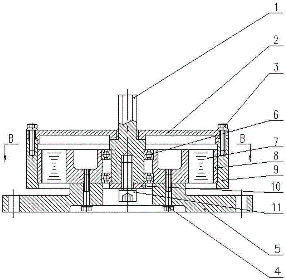
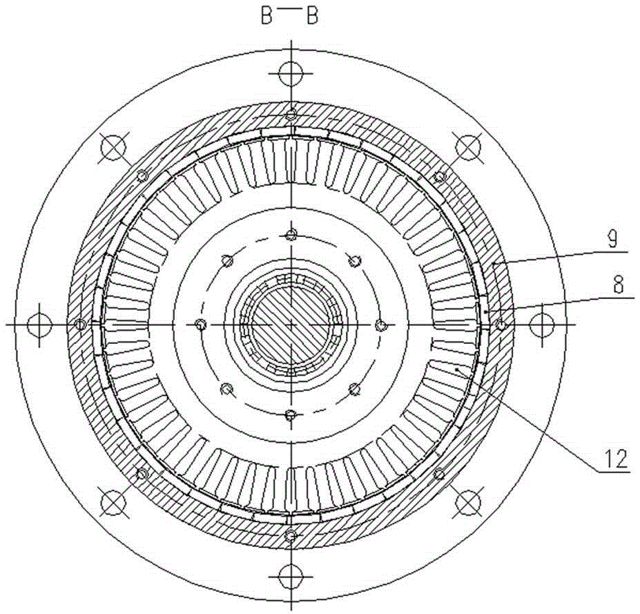
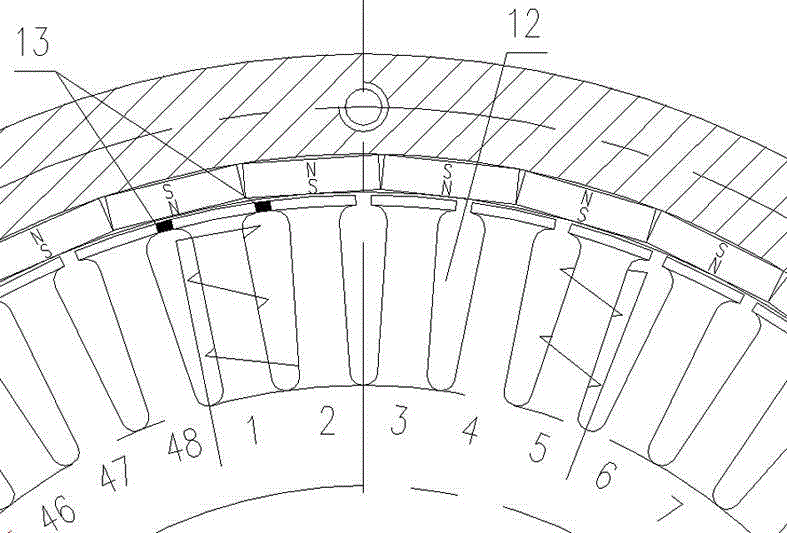
[0013] Please refer to Figure 1 to Figure 3 , The improved rotary magnetic device of the present invention includes: a stator assembly and a rotor assembly, and the stator assembly includes a stator core 7 and a coil. Several pear-shaped slots 12 are opened on the circumference of the stator core 7, and Hall sensors 13 connected with the control system are arranged in the pear-shaped slots. The coil is wound on the stator core 7, and the coil is controlled by the control system through the lead wire. The stator core 7 is connected to the support seat 5 of the device through several third bolts 4 . A washer is also provided between the third bolt and the supporting seat. The ro...


PUM


Abstract

The present invention discloses a rotary magnetic device. The rotary magnetic device comprises a stator assembly and a rotor assembly. The stator assembly comprises a stator core and a coil; the circumference of the stator core is provided with a plurality of pear-shaped grooves, the grooves are provided with Hall sensors connected to a control system; the coil is wound on the stator core and is subjected to the control of the control system; and the stator core is connected to a supporting base of the device through a bolt. The rotor assembly comprises a magnetic sheet, a drum, a cover and an output shaft, the circumference of the magnetic sheet is uniformly adhered to the inside wall of the drum; the output shaft is connected to a thread of the cover; the cover connected to the drum through a bolt; and the rotor assembly is connected to the rotor assembly through a bearing of the output shaft. Advantages of the rotary magnetic device disclosed by the present invention are that: the device size is reduced, a mechanical structure is simplified, all intermediate transmission chains are eliminated, and the electromagnetic force is directly output to push the device to operate; and not only reliability, rapidity and controllability of the performance are improved, and output efficiency is improved, but also production costs are reduced in the economic aspect.

Description

technical field [0001] The invention relates to a rotary magnetic device. Background technique [0002] In the prior art, most of the isolating switches and earthing switches of gas-insulated metal-enclosed switchgear at home and abroad use spring operating mechanisms or electric mechanisms. The spring operating mechanism uses the principle of spring symmetry over center, through the forward and reverse function of the motor, the mechanism compresses the spring to realize the opening and closing; the electric mechanism uses the forward and reverse rotation function of the motor to ensure the opening and closing position with clutch and worm gear transmission and output angle. Both of these mechanisms require intermediate energy storage or deceleration transmission links to complete the action, and there are the following problems: first, due to the deceleration transmission, the wear process between parts is increased, which directly affects the stability of the mechanism; ...

Claims


Application Information

Patent Timeline
Patent Type & Authority Applications(China)
IPC IPC(8): H01H3/28H02K11/215
CPCH01H3/28
Inventor 何志猛王刚乔丹董建威
Owner 北京北开电气股份有限公司
Why Eureka
Try Eureka