Dynamo-electric machine with reluctance and permanent magnet rotor

A rotor and machine technology, applied in the direction of electromechanical devices, magnetic circuit rotating parts, magnetic circuits, etc., can solve the problems of high torque fluctuation, low power density, etc., and achieve small torque fluctuation, high power density, high critical rotational speed moment effect

Inactive Publication Date: 2016-03-09
SIEMENS AG
View PDF5 Cites 7 Cited by
  • Summary
  • Abstract
  • Description
  • Claims
  • Application Information

AI Technical Summary

Problems solved by technology

Furthermore, a disadvantage here is the relatively too low power density and the relatively too high torque fluctuations of the electromechanical machine

Method used


Image

  • Dynamo-electric machine with reluctance and permanent magnet rotor
  • Dynamo-electric machine with reluctance and permanent magnet rotor
  • Dynamo-electric machine with reluctance and permanent magnet rotor

Examples


Embodiment Construction

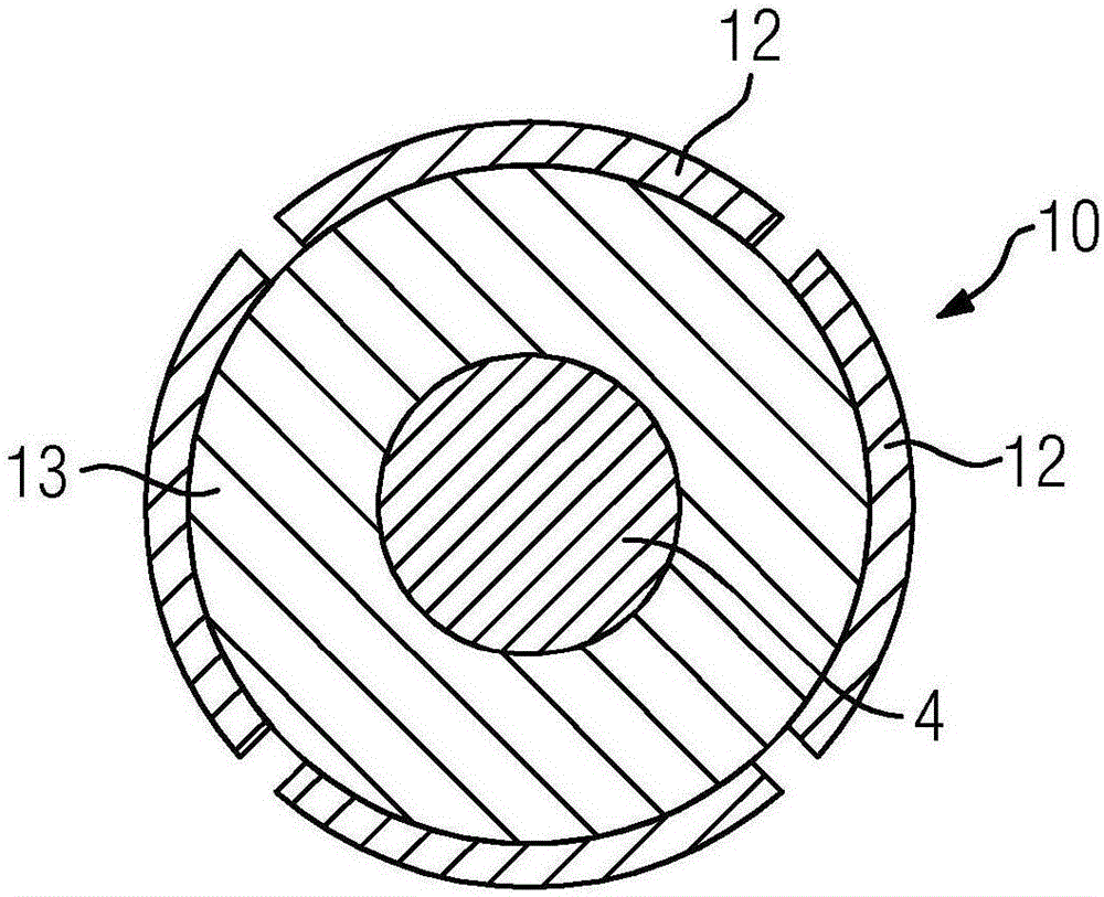
[0025] Figure 8 A reluctance motor with magnetic support is shown, in which an additional permanent magnet 12 is arranged in a flux lock 14 .

[0026] also, Figure 9 A known rotor type is shown in which each pole of the permanent magnets 12 forms a V-shaped arrangement and by means of this arrangement an additional reluctance support is obtained.

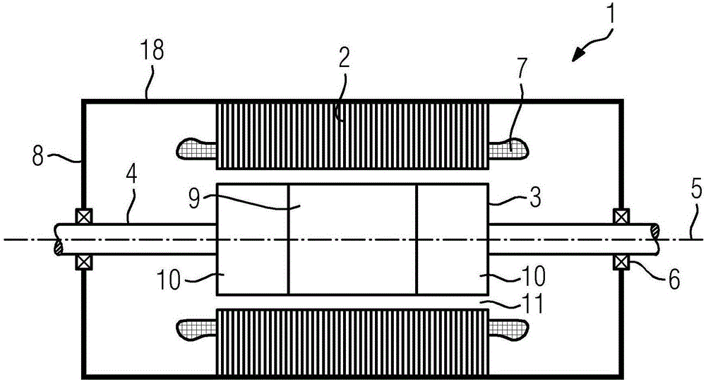
[0027] figure 1 A schematic diagram of an electromechanical machine 1 according to the invention is shown in longitudinal section with a stator 2 in which a winding system (not shown in detail) is arranged, which forms a winding head 7 on the front side of the stator 2 .

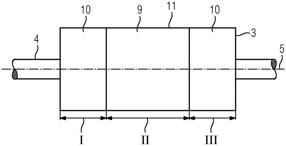
[0028] The stator 2 is arranged in a housing 18 . also, figure 1 A rotor 3 according to the invention is shown having three sections directly axially adjoining one another, which are positioned on a shaft 4 , wherein the shaft 4 is held by a bearing 6 and a corresponding end shield 8 .

[0029] In this case, the central section has a magneto-resistive lamin...


PUM


Abstract

The invention relates to a rotor (3) of a dynamo-electric machine (1) which is rotatable about an axis (5), wherein the rotor (3) consists of at least three axial successively arranged immediately adjacent sections I to III composed, wherein the rotor ( 3) is formed by at least two different rotor part package types (9,10).

Description

technical field [0001] The invention relates to a rotor of an electromechanical machine, which is rotatable about an axis, wherein the rotor has a reluctance section and a permanent magnet section arranged axially in succession. Furthermore, the invention relates to an electromechanical machine with a rotor and the use of such a machine. Background technique [0002] The electromechanical machine has a rotor via which torque is transmitted to the work machine or a conversion into electrical energy takes place, for example in generator operation of the electromechanical machine. The disadvantage here is that each rotor type, namely permanently excited rotors, electrically excited rotors, cage armature rotors, reluctance rotors, has the disadvantage that additionally the operating or energy acquisition requirements of the working machine are increased. difficulty. [0003] Thus far, rotor structures have been realized in which magnets are present in the rotor laminations and...

Claims


Application Information

Patent Timeline
IPC IPC(8): H02K1/22H02K1/27
CPCH02K1/246H02K1/2753H02K16/02H02K19/103H02K29/03H02K2201/06
Inventor 伊瓦·特雷莎·塞尔纳-卡尔沃罗尔夫·福尔默
Owner SIEMENS AG
Why Eureka
Try Eureka