
Method for measuring actual output impedance of transmitter

A technology of actual output and transmitter, applied in the direction of transmitter monitoring, etc., can solve the problems of radio frequency final power device, vacuum device tube damage, antenna feeder system radiation efficiency reduction, standing wave ratio, etc., to improve reliability, Improved radiation efficiency and low reflected power

Active Publication Date: 2016-03-09
SHAANXI FENGHUO ELECTRONICS
View PDF6 Cites 7 Cited by
  • Summary
  • Abstract
  • Description
  • Claims
  • Application Information

AI Technical Summary

Problems solved by technology

[0004] In practical applications, it is found that the frequency point where the antenna tuner successfully tunes with micropower has a relatively small standing wave (matched to around 50Ω), but when transmitting at high power, the standing wave ratio becomes larger, resulting in a larger reverse power of the transmitter , the radiation efficiency of the antenna feed system is reduced
When the standing wave ratio becomes larger and the antenna system has no resonance, there is a large reactive component in the impedance, which may cause damage to the RF final power device, vacuum device and electron tube inside the transmitter.

Method used


Image

  • Method for measuring actual output impedance of transmitter
  • Method for measuring actual output impedance of transmitter
  • Method for measuring actual output impedance of transmitter

Examples


Embodiment Construction

[0028] The following will clearly and completely describe the technical solutions in the embodiments of the present invention with reference to the accompanying drawings in the embodiments of the present invention. Obviously, the described embodiments are only some, not all, embodiments of the present invention. Based on the embodiments of the present invention, all other embodiments obtained by persons of ordinary skill in the art without making creative efforts belong to the protection scope of the present invention.

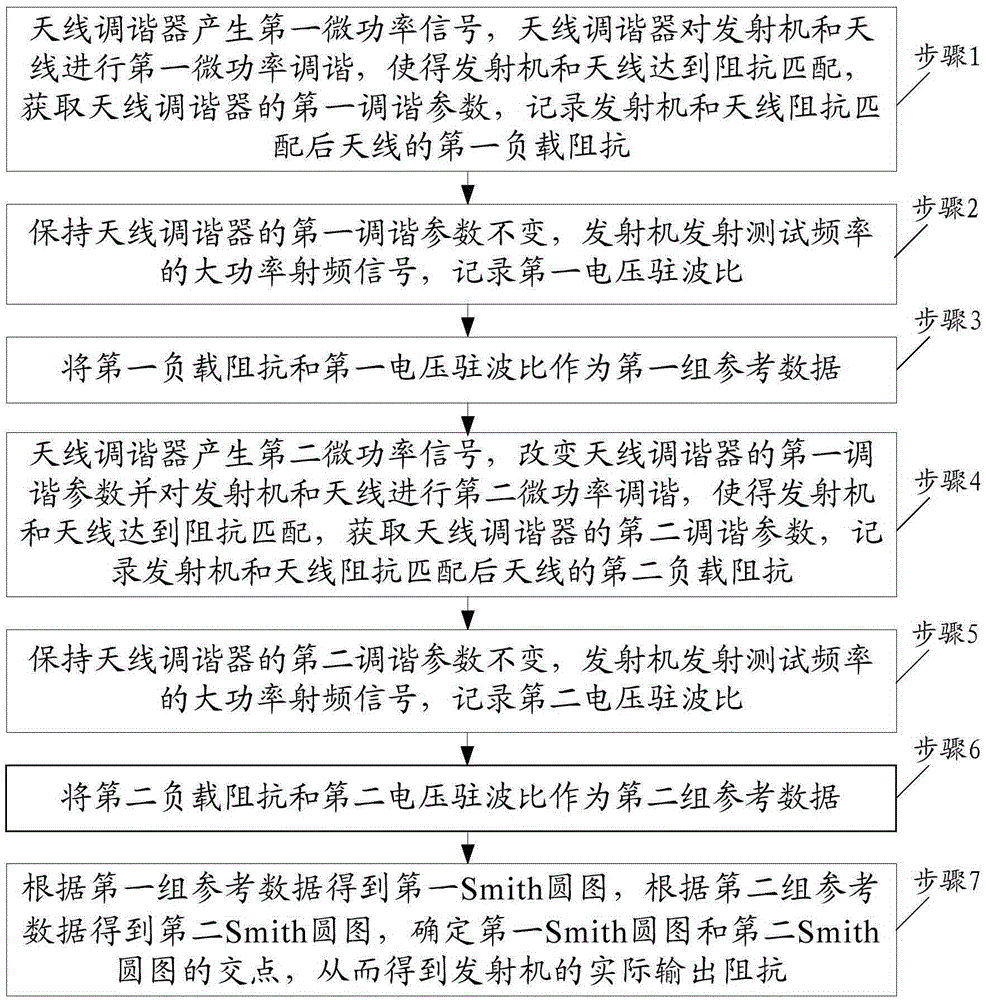
[0029] An embodiment of the present invention provides a method for measuring the actual output impedance of a transmitter, and the method is used for impedance matching of an antenna tuning system, such as figure 1 As shown, the method includes:

[0030] Step 1, the antenna tuner generates the first micro-power signal, and the antenna tuner performs the first micro-power tuning on the transmitter and the antenna, so that the transmitter and the antenna achiev...


PUM


Abstract

The invention relates to the technical field of communication equipment application, in particular to a method and a system for measuring actual output impedance of a transmitter, suitable for a system for realizing impedance matching between the transmitter and an antenna by an antenna tuner. The method comprises the steps that the antenna tuner generates a first micropower signal, performs first micropower tuning on the transmitter and the antenna, so that the transmitter and the antenna achieve impedance matching, and first load impedance of the antenna is recorded after the impedance matching between the transmitter and the antenna; parameters of the antenna tuner are kept unchanged, the transmitter transmits a high-power radio-frequency signal with a specific frequency, and a first voltage standing wave ratio is recorded, wherein the first load impedance and the first voltage standing wave ratio are taken as a first group of reference data; the process is repeated to acquire a second group of reference data; according to the first group of reference data and the second group of reference data, the actual output impedance of the transmitter is obtained.

Description

technical field [0001] The invention relates to the technical field of communication equipment application, in particular to a method for measuring the actual output impedance of a transmitter, which is suitable for a system in which an antenna tuner is used to realize impedance matching between a transmitter and an antenna. Background technique [0002] The effect of short-wave communication is closely related to factors such as antenna bandwidth, gain, standing wave ratio, and directivity. Therefore, in short-wave communication, it is extremely important to choose a good antenna to improve the communication effect. In the short-wave frequency band, due to the large band coverage and strong changes in antenna parameters, it is difficult to use a conventional broadband matching network to achieve fast impedance matching for various antennas. The short-wave transmitter must use an antenna tuner to complete the impedance of the transmitter and antenna before working. Matching...

Claims


Application Information

Patent Timeline
Patent Type & Authority Applications(China)
IPC IPC(8): H04B17/10
Inventor 张志刚郑丙寅徐海涛郑宏星郑斌
Owner SHAANXI FENGHUO ELECTRONICS
Learn More