
Vessel forceps

A technology of vascular forceps and forceps mouth, which is applied in the field of vascular forceps, can solve the problems of rough liver incision by finger pinching, limited CUSA, and contradictory precise liver resection, so as to achieve convenient crushing and separation, less liver damage, The effect of reducing the amount of bleeding

Active Publication Date: 2016-03-16
蔡建强
View PDF4 Cites 3 Cited by
  • Summary
  • Abstract
  • Description
  • Claims
  • Application Information

AI Technical Summary

Problems solved by technology

Among many methods, CUSA, finger pinching method and fine forceps liver cutting method are currently the main methods of liver isolation, but CUSA is limited by advanced and expensive equipment and cannot be widely used in economically backward areas; finger pinching method Liver resection is relatively rough, which is contrary to the concept of "precise liver resection". According to the data, the precise clamping method of blood vessel forceps is still a commonly used liver cutting technique in clinical practice. A finer level of manipulation is still possible
However, the vascular forceps (such as Kelly forceps) commonly used in the current clamping method have sharp toothed racks distributed on the closed surfaces of the two jaws, which easily damage the bile ducts or blood vessels distributed therein (for example, hepatic veins) while crushing the liver parenchyma. The wall of the branch is thin, easily damaged and bleeding), which affects the effect of the operation, so how to improve the structure of the vascular clamp to avoid damaging the bile duct or blood vessels during the operation and reduce the risk of operation is a technical problem that needs to be solved

Method used


Image

  • Vessel forceps
  • Vessel forceps
  • Vessel forceps

Examples


Embodiment Construction

[0029] The technical solutions of the present invention will be further described below in conjunction with the embodiments and the accompanying drawings.

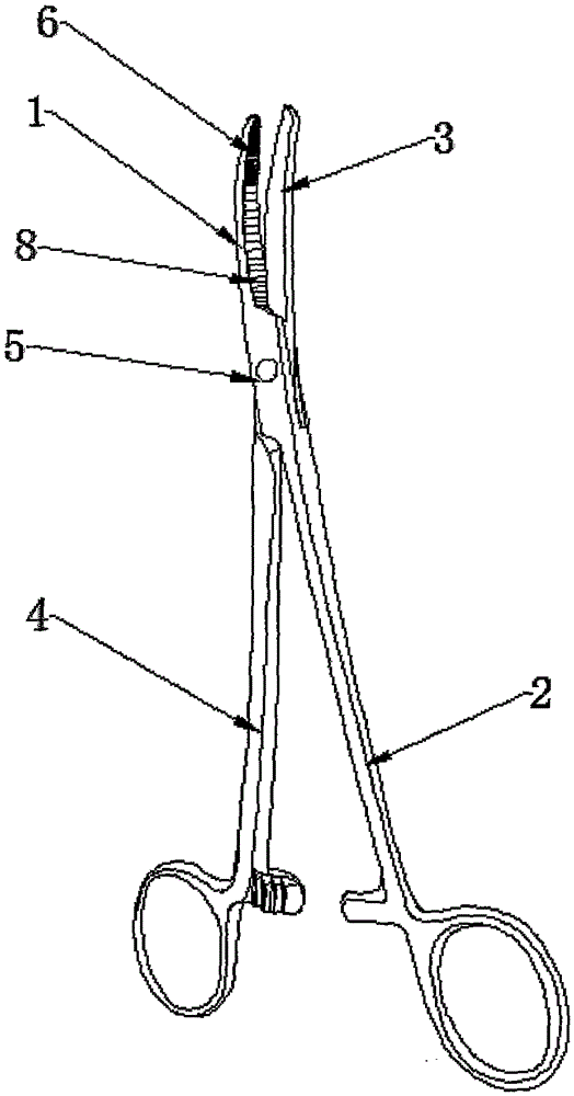
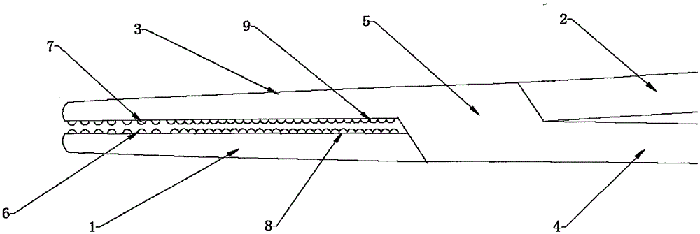
[0030] see figure 1 , the present embodiment provides a kind of vascular forceps, comprising a first forceps body and a second forceps body, the first forceps body and the second forceps body are mutually hinged; the first forceps body comprises a first forceps mouth 1 and a first forceps Arm 2, the second pliers body includes a second pliers mouth 3 and a second pliers arm 4, the first pliers arm 2 and the second pliers arm 4 can be closed or opened with the hinge 5 as the center of activity, And the first pliers mouth 1 and the second pliers mouth 3 can be mutually closed or opened under the drive of the first pliers arm 2 and the second pliers arm 4; the closing of the first pliers mouth 1 A plurality of first protrusions 6 are arranged on the surface, and when the first pliers mouth 1 and the second pliers mouth 3 are...


PUM


Abstract

The invention discloses vessel forceps. The vessel forceps comprise a first forceps body and a second forceps body which are hinged together, wherein the first forceps body comprises a first forceps mouth and a first forceps arm, the second forceps body comprises a second forceps mouth and a second forceps arm, the first forceps arm and the second forceps arm can be closed or opened by taking the hinging part as the moving center, and the first forceps mouth and the second forceps mouth are closed or opened under the driving of the first forceps arm and the second forceps arm; a plurality of first bulges are arranged on the closed face of the first forceps mouth, when the first forceps mouth and the second forceps mouth are closed, the plurality of first bulges contact the closed face of the second forceps mouth, when the structure is used for clamping the liver parenchymal tissue to be broken, the plurality of bulges can extrude blood vessels or biliary ducts distributed in the liver tissue to be positioned in the gaps among the bulges, so that the risk that a sharp multi-rack structure easily damages the biliary ducts or the blood vessels is reduced, and a doctor can carry out accurate clamping and dividing operations on the liver parenchyma.

Description

technical field [0001] The invention relates to the technical field of medical instruments, in particular to a blood vessel clamp. Background technique [0002] With the development of liver surgery, various liver cutting techniques are constantly emerging, such as finger pinching, vascular forceps, fine clamping liver cutting technology, ultrasonic suction knife (CUSA), water knife, Tissuelink electric knife, harmonic knife and other advanced operations Instrumental liver resection techniques are gradually applied in clinical practice, the purpose of which is to quickly separate the liver parenchyma, reduce the amount of bleeding, and seal the bile duct to avoid postoperative bile leakage. Among many methods, CUSA, finger pinching method and fine forceps liver cutting method are currently the main methods of liver isolation, but CUSA is limited by advanced and expensive equipment and cannot be widely used in economically backward areas; finger pinching method Liver resecti...

Claims


Application Information

Patent Timeline
IPC IPC(8): A61B17/12A61B17/28
CPCA61B17/12009A61B17/282A61B2017/12004
Inventor 蔡建强
Owner 蔡建强
Learn More