U-type clamping claw self-centering rotary device

A rotary device, self-centering technology

Active Publication Date: 2018-02-09
HIMILE MECHANICAL MFG
View PDF6 Cites 0 Cited by
  • Summary
  • Abstract
  • Description
  • Claims
  • Application Information

AI Technical Summary

Problems solved by technology

[0004] The technical problem to be solved by the present invention is to provide a high-quality processed workpiece, which can effectively avoid the axial movement of the workpiece, effectively ensure the supply and processing accuracy, and have high processing efficiency, which can compensate for the large through-hole welding card. The lack of difficulty in picking and placing long and heavy workpieces on the plate can effectively reduce the processing cost of the U-type clamping claw self-centering rotary device

Method used


Image

  • U-type clamping claw self-centering rotary device
  • U-type clamping claw self-centering rotary device
  • U-type clamping claw self-centering rotary device

Examples


Embodiment Construction

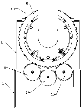
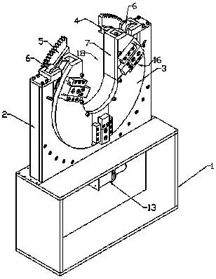
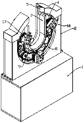
[0051] Examples such as Figure 1-Figure 13 As shown, the U-type clamping claw self-centering rotary device includes a base 1, and a support plate 2 is fixedly connected to the base 1. The support plate 2 has an opening, and a self-centering clamping mechanism 18 for tightening the workpiece is provided in the opening. .

[0052] The self-centering clamping mechanism 18 includes three clamping claws 16 , which are connected by a transmission mechanism 8 , and the three clamping claws can realize linkage under the action of the transmission mechanism 8 .

[0053] The self-centering clamping mechanism 18 also includes a turntable 4, three clamping claws 16 are evenly distributed around the center of the turntable 4, the angle between two adjacent clamping claws 16 is 120 degrees, and the transmission mechanism 8 can drive The three clamping claws 16 move synchronously towards the center of the turntable 4 .

[0054] The turntable 4 is provided with a U-shaped opening capable o...


PUM


Abstract

The invention discloses a U-type self-centering slewing device adopting clamping jaws. The device comprises a self-centering clamping mechanism, wherein the self-centering clamping mechanism comprises three clamping jaws which are in transmission connection through a transmission mechanism; and three clamping jaws can achieve linkage under the action of the transmission mechanism. According to the technical scheme, a processed workpiece is high in quality; the workpiece can be effectively prevented from shifting axially; the feeding and processing accuracy can be effectively guaranteed; the processing efficiency is high; the deficiency that a longer or heavier workpiece is placed into or taken out of a large-through-hole welding chuck difficultly can be made up; and the processing cost can be effectively reduced.

Description

technical field [0001] The invention relates to a tooling tool for automatic welding of circular workpieces and flame drilling and blanking, especially a U-type clamp used for automatic welding of some long pipe fittings and workpieces with flanges at both ends. Self-centering slewing device with claws. Background technique [0002] In petroleum, natural gas, chemical and other industries, it is necessary to process round workpieces, such as pipe cutting, drilling, welding, etc. Since there are many types and specifications of the workpieces to be processed, and the sizes are different, it brings a lot of inconvenience to the processing. Generally speaking, simple tools such as roller frames are used to manually cut, open holes, weld, etc. The accuracy of this method cannot be guaranteed, and the quality of the processed workpieces is poor, and the processing efficiency is low and the cost is high. [0003] In addition, the roller frame is used to drive the tool, which is ...

Claims


Application Information

Patent Timeline
Patent Type & Authority Patents(China)
IPC IPC(8): B23K37/053B23K7/10
CPCB23K7/10B23K37/053
Inventor 姜雄德魏效辉王莲荣秦启伟迟丰涛魏猛
Owner HIMILE MECHANICAL MFG
Why Eureka
Try Eureka