Stretcher leveler chain drive lifting pin mechanism with guiding

A technology of a straightening machine chain and a transmission mechanism, applied in the field of forging equipment, can solve the problems of easy slippage, different lifting heights, great danger, etc., and achieve the effects of reducing movement asynchrony, improving work efficiency, and improving service life.

Active Publication Date: 2013-04-10
DALIAN DESIGN INST CO LTD CHINA FIRST HEAVY IND +1
View PDF6 Cites 0 Cited by
  • Summary
  • Abstract
  • Description
  • Claims
  • Application Information

AI Technical Summary

Problems solved by technology

[0002] The traditional pin lifting mechanism of stretching straightening machine uses unguided steel wire rope to transmit power and movement. The disadvantages of the traditional pin lifting mechanism are: low efficiency, easy to slip, and high risk; the pin lifting movement on both sides of the pin cylinder Synchronous movement cannot be guaranteed, resulting in different lifting heights on both sides during the lifting process. Often one side is lifted very high, and the lifting pin on the other side has not come out of the compression column, which makes the adjustment of the fixed chuck very inconvenient; the pulley movement has no guide, once the lifting pin moves Uneven stress occurs during the process, and the piston rod in the hydraulic cylinder will rotate slightly under the action of the fixed pulley, which will greatly damage the seal of the hydraulic cylinder, and in severe cases will cause the piston rod to bend, which will have a great impact Service life of hydraulic cylinder

Method used


Image

  • Stretcher leveler chain drive lifting pin mechanism with guiding
  • Stretcher leveler chain drive lifting pin mechanism with guiding
  • Stretcher leveler chain drive lifting pin mechanism with guiding

Examples


Embodiment Construction

[0016] The present invention will be further described below in conjunction with drawings and embodiments.

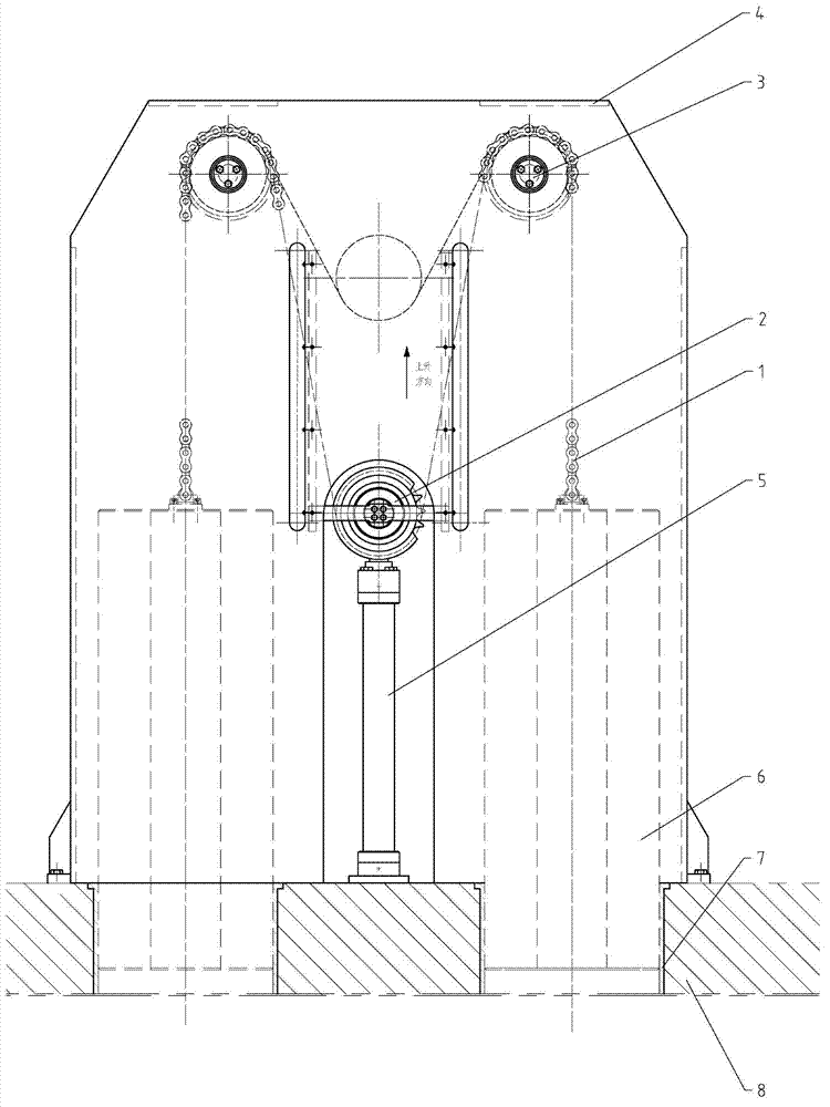
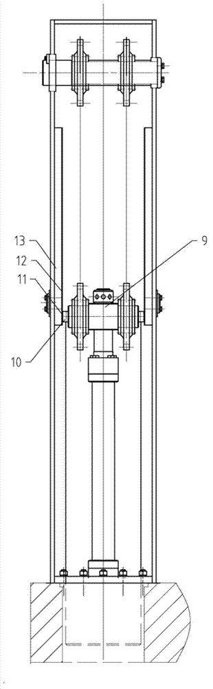
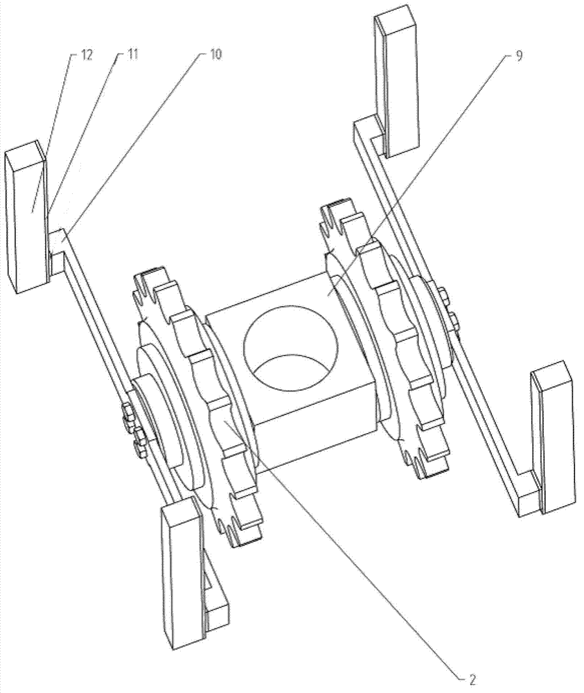
[0017] Tension leveler chain drive pin lifting mechanism with guide, including hanger, pin cylinder, compression column, crosshead, lifting pin, roller chain, fixed sprocket, moving sprocket, sprocket guide rail, copper slide plate and hanger The frame guide rail, the bolt cylinder is fixed on the compression column, the crosshead is connected to the bolt cylinder, the two fixed sprockets are fixedly installed on both sides of the crosshead, the inner side of the fixed pulley is connected to the crosshead, and the two fixed sprockets are respectively located on the bolt cylinder On both sides, the fixed sprocket does not rotate, and the two moving sprockets are installed on the hanger above the fixed sprocket through the shaft. One end of the roller chain is fixed on the fixed sprocket, and the other end is connected to the lifting pin around the moving sprocket. The wh...


PUM


Abstract

The invention discloses a stretcher leveler chain drive lifting pin mechanism with guiding. The stretcher leveler chain drive lifting pin mechanism with the guiding comprises a hanging bracket, a bolt cylinder, compression columns, a crosshead, lifting pins, two roller chains, two fixed chain wheels, two moving chain wheels, a chain wheel guide rail, copper sliding plates and hanging bracket guide rails, wherein the two fixed chain wheels are respectively and fixedly arranged at both sides of the crosshead; the two moving chain wheels are arranged on the hanging bracket above the fixed chain wheels through a chain wheel shaft; one ends of the two roller chains are respectively and fixedly arranged on the two fixed chain wheels; the other ends of two the roller chains respectively bypass the moving chain wheels to be respectively connected onto the lifting pins; the chain wheel guide rails are respectively and fixedly arranged at the outer sides of the fixed chain wheels; the hanging bracket guide rails are respectively arranged on pillars of the hanging bracket; the copper sliding plates are arranged on surfaces of the hanging bracket guide rails; and the chain wheel guide rails are respectively abutted with the copper sliding plates on the surfaces of the hanging bracket guide rails. The stretcher leveler chain drive lifting pin mechanism with the guiding has the beneficial effects that elastic sliding or slipping does not occur during chain drive, so that the average drive ratio is stable and accurate, and the synchronism and the work efficiency of the movement of every lifting pin can be improved; the deflection of a piston rod is avoided; the service life of the hydraulic cylinder is prolonged; and chain drive tension is low, so that pressure acting on the chain wheel shaft is also low.

Description

technical field [0001] The invention belongs to the technical field of forging equipment, in particular to a pin-lifting mechanism of a stretching straightening machine. Background technique [0002] The traditional pin lifting mechanism of stretching straightening machine uses unguided steel wire rope to transmit power and movement. The disadvantages of the traditional pin lifting mechanism are: low efficiency, easy to slip, and high risk; the pin lifting movement on both sides of the pin cylinder Synchronous movement cannot be guaranteed, resulting in different lifting heights on both sides during the lifting process. Often, one side is lifted very high, and the lifting pin on the other side has not come out of the compression column, which makes the adjustment of the fixed chuck very inconvenient; the pulley movement has no guide, once the lifting pin moves Uneven stress occurs during the process, and the piston rod in the hydraulic cylinder will rotate slightly under the...

Claims


Application Information

Patent Timeline
Patent Type & Authority Applications(China)
IPC IPC(8): B21D1/00B21D3/00
Inventor 王超孙远国
Owner DALIAN DESIGN INST CO LTD CHINA FIRST HEAVY IND
Why Eureka
Try Eureka