
Rolling barrel electroplating device

An electroplating device and drum technology, applied in the electrolysis process, electrolysis components, etc., can solve the problems that are contrary to the development direction of relay product surface electroplating, the electric wire is easy to be twisted, damaged, and the cost of material and labor is large, so as to save material cost and Effects of maintenance cost, labor cost reduction, and plating time shortening

Active Publication Date: 2016-03-16
厦门金越电器有限公司
View PDF10 Cites 2 Cited by
  • Summary
  • Abstract
  • Description
  • Claims
  • Application Information

AI Technical Summary

Problems solved by technology

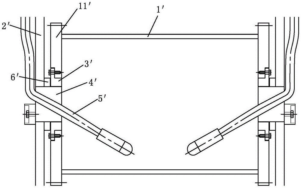
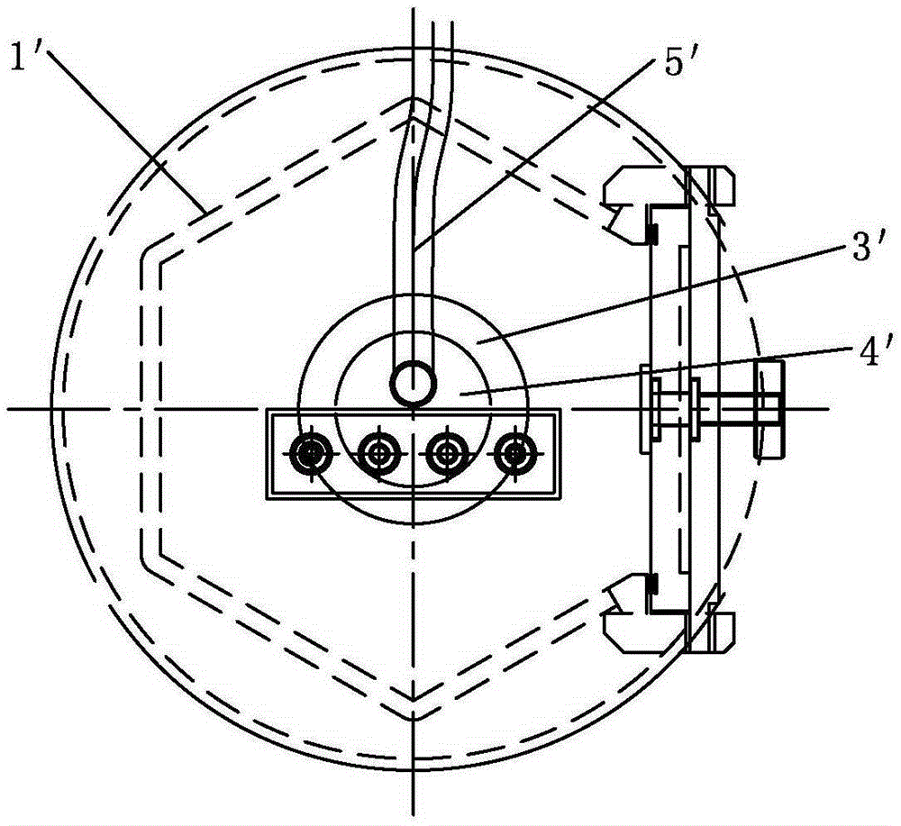
[0004] Yet the problem that above-mentioned drum electroplating equipment brings is: firstly, electric wire 5 ' stirs inside drum 1 ', realizes electric conduction function and beats parts like hammer again at the same time, just the deformation rate of parts increases greatly, especially For small and thin parts
Secondly, the electric wire 5' itself is also very easy to be twisted and damaged, resulting in frequent replacement and high material and labor costs.
These are contrary to the development direction of the surface plating of relay products

Method used


Image

  • Rolling barrel electroplating device
  • Rolling barrel electroplating device
  • Rolling barrel electroplating device

Examples


Embodiment Construction

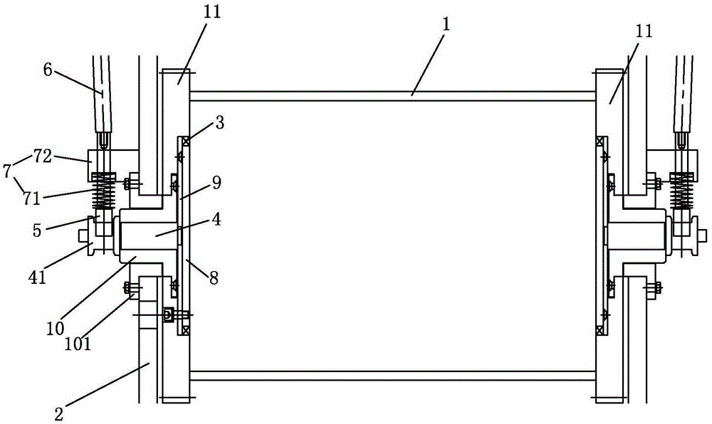
[0031] example, see Figure 3-Figure 6 As shown, a drum electroplating device of the present invention includes a bracket 2 and a drum 1. The drum 1 is a hollow structure, and the two ends of the drum 1 are respectively formed or fixedly connected to one end cover 11. The drum 1 passes through the two The end cover 11 is rotatably connected to the bracket 2 ; the side wall of the drum 1 is also mounted with a movable cover 13 for parts to enter and exit the drum 1 , and the movable cover 13 is locked by a locking mechanism 14 . The present invention also includes two conductive mechanisms that cooperate with the two end covers 11 one by one, the two conductive mechanisms respectively include a conductive bush 5 for connecting the cable 6, a planar conductive member and a conductive shaft 4; the conductive member is installed on the On the inner end surface of the end cover 11, the conductive shaft 4 is fixed on the end cover 11 and is located at the rotation axis of the end co...


PUM


Abstract

The invention discloses a rolling barrel electroplating device. The rolling barrel electroplating device comprises a bracket and a rolling barrel; the rolling barrel is a hollow structure, and the two ends of the rolling barrel are respectively molded or fixedly connected with end covers; and the rolling barrel is rotationally connected to the bracket through the two end covers. The rolling barrel electroplating device further comprises two electric conducting mechanisms matched with the two end covers one to one; the two electric conducting mechanisms respectively comprise electric conducting bearing bushes for connecting with cables, surface-shaped electric conducting parts and electric conducting shafts; the electric conducting parts are mounted on the inner end surfaces of the end covers; the electric conducting shafts are fixed on the end covers, and are positioned on the rotating axis of the end covers; the electric conducting shafts are electrically connected with the electric conducting parts; and the electric conducting bearing bushes are positioned out of the rolling barrel, and are tightly pressed on the side surfaces of the electric conducting shafts through elastic positioning mechanisms. The rolling barrel electroplating device adopts the structure, is less in wear and durable, saves the material cost and the maintenance cost caused by frequent replacement of electric leads in the prior art, solves the problem of deformation of small sheet type parts due to the beating of the electric leads, and reduces the labor cost caused by subsequent classification of bad parts through labors.

Description

technical field [0001] The invention relates to an electroplating device, in particular to a barrel electroplating device. Background technique [0002] With the development of relay products in the direction of miniaturization and precision, the parts in relay products are getting smaller and thinner. The surface plating of metal parts is not suitable for rack plating because the parts are too small, and only barrel plating can be used to achieve mass production. [0003] It is a common practice in the industry for drum electroplating equipment to use electrical wires to conduct electricity. The prior art drum electroplating equipment such as figure 1 , figure 2 As shown, the end covers 11' at both ends of the drum 1' are respectively connected to the bracket 2' by the shaft sleeve 3' in cooperation with the shaft core 4'. Specifically, the shaft sleeve 3' is fixed to the end cover 11' of the drum through screws At the same time, the shaft core 4' is fixed with the bra...

Claims


Application Information

Patent Timeline
IPC IPC(8): C25D17/20
Inventor 李国华方国富
Owner 厦门金越电器有限公司
Learn More