Offshore floating type draught fan and draught fan foundation thereof

A wind turbine foundation and floating technology, which is applied in the installation/support of wind turbine configuration, wind power generation, floating buildings, etc., can solve the problems of increasing project cost, large movement range, and increasing design difficulty, so as to improve impact resistance and Anti-fatigue performance, reduced heave and rotation, large seawater action area

Inactive Publication Date: 2016-03-16
NEW UNITED GROUP
View PDF7 Cites 9 Cited by
  • Summary
  • Abstract
  • Description
  • Claims
  • Application Information

AI Technical Summary

Problems solved by technology

Among them, the single column buoy structure, three buoy foundation and semi-submersible structure are positioned by catenary lines or anchor chains, which are prone to large pitching, rolling, rotating and heaving under the action of wind and waves, so that the wind turbine cannot In normal operation, in order to reduce the range of movement of the fan, it is usually necessary to set up a damping system separately, which not only increases the difficulty of design, but also increases the cost of the project
The tension leg platform foundation is positioned by the tension leg system. The tension leg is generally anchored vertically on the seabed. The buoyancy of the platform is greater than gravity. The tension leg needs to provide a large pre-tension to balance the buoyancy of the buoy and maintain the balance and stability of the unit. The sway is small, but the range of motion in the horizontal direction is large, and the tension leg is prone to damage in severe sea conditions, causing the wind turbine to lose balance

Method used


Image

  • Offshore floating type draught fan and draught fan foundation thereof
  • Offshore floating type draught fan and draught fan foundation thereof
  • Offshore floating type draught fan and draught fan foundation thereof

Examples


Embodiment Construction

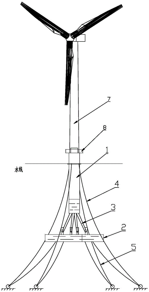
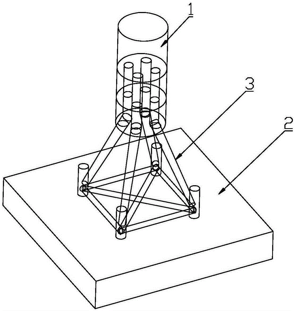
[0024] like figure 1 , 2 , 3 and 4, a offshore floating wind turbine foundation, including a buoy structure 1, a support structure, a ballast tank 2, an upper fixing device and a lower fixing device, the ballast tank 2 is located below the buoy structure 1, and the buoy structure 1 It is connected with the ballast tank 2 through a bracket structure, which increases the length of the entire wind turbine foundation, moves the center of gravity of the structure down, and increases the moment of inertia of the wind turbine tower and the foundation structure and the moment of the reverse couple.

[0025] The buoy structure 1 is a single buoy structure.

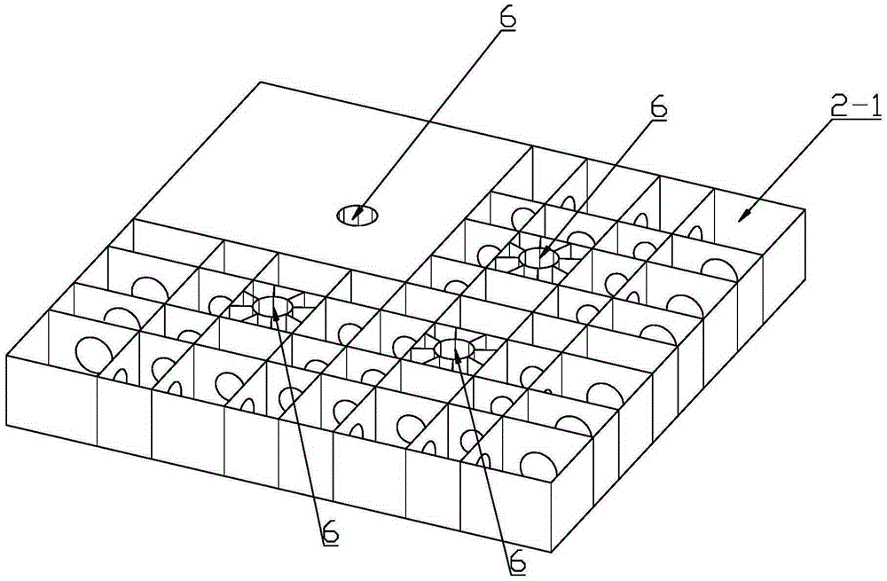
[0026] The ballast tank 2 is a flat box structure, the outer contour of the ballast tank 2 is larger than the outer contour of the buoy structure 1, and the interior of the ballast tank 2 is divided into a plurality of independent cabins 2-1, and the independent cabin 2-1 passes through the ballast tank The water volume adjustmen...


PUM


Abstract

The invention relates to an offshore floating type draught fan and a draught fan foundation thereof. The draught fan foundation comprises a floating barrel structure, a support structure, a ballast tank, an upper-layer fixing device and a lower-layer fixing device. The ballast tank is located below the floating barrel structure. The floating barrel structure and the ballast tank are connected through the support structure. The ballast tank is of a flat box structure, and the outer contour of the ballast tank is larger than that of the floating barrel structure. The upper-layer fixing device comprises a plurality of upper-layer cables, the upper-layer cables are evenly distributed around the floating barrel structure, the upper ends of the upper-layer cables and the floating barrel structure are fixed, and the lower ends of the upper-layer cables and the seabed are fixed. The lower-layer fixing device comprises a plurality of lower-layer cables, the lower-layer cables are evenly distributed around the ballast tank, the upper ends of the lower-layer cables and the ballast tank are fixed, and the lower ends of the lower-layer cables and the seabed are fixed. The offshore floating type draught fan and the draught fan foundation thereof have the beneficial effects of being simple in structure, good in stability, not likely to be damaged, high in adaptability to water depth and especially suitable for sea areas with large water depth.

Description

technical field [0001] The invention relates to an offshore floating fan and its foundation. Background technique [0002] The existing floating offshore wind turbine foundations mainly include single column buoy foundation, three buoy foundation, semi-submersible foundation and tension leg foundation. Among them, the single column buoy structure, three buoy foundation and semi-submersible structure are positioned by catenary lines or anchor chains, which are prone to large pitching, rolling, rotating and heaving under the action of wind and waves, so that the wind turbine cannot In normal operation, in order to reduce the movement range of the fan, it is usually necessary to set up a damping system separately, which not only increases the design difficulty, but also increases the project cost. The tension leg platform foundation is positioned by the tension leg system. The tension leg is generally anchored vertically on the seabed. The buoyancy of the platform is greater t...

Claims


Application Information

Patent Timeline
Patent Type & Authority Applications(China)
IPC IPC(8): F03D13/25B63B35/44B63B21/50
CPCY02E10/727B63B35/44B63B21/50
Inventor 张力伟郭庭福鲍玉亮徐铭
Owner NEW UNITED GROUP
Why Eureka
Try Eureka