a centrifugal clutch

A centrifugal clutch and shaft center technology, applied in the mechanical field, can solve problems such as complex clutches and inability to achieve automatic adjustment, and achieve the effect of ensuring coaxiality

Active Publication Date: 2018-10-09
江苏绿源健康铝箔科技有限公司
View PDF5 Cites 0 Cited by
  • Summary
  • Abstract
  • Description
  • Claims
  • Application Information

AI Technical Summary

Problems solved by technology

[0003] Existing clutches are usually magnetic powder, electromagnetic, friction or hydraulic, and the on-off is controlled by the input of the control device. For the power system that needs to start dragging and disconnect at high speed, the use of the above-mentioned clutch is usually too complicated. And need human control, can not achieve automatic adjustment

Method used


Image

  • a centrifugal clutch

Examples


Embodiment Construction

[0015] The following will clearly and completely describe the technical solutions in the embodiments of the present invention. Obviously, the described embodiments are only some of the embodiments of the present invention, rather than all the embodiments. Based on the embodiments of the present invention, all other embodiments obtained by persons of ordinary skill in the art without making creative efforts belong to the protection scope of the present invention.

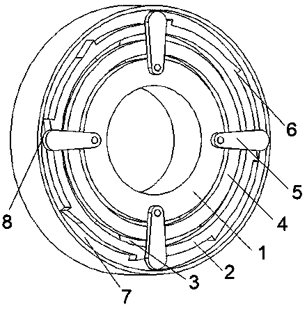
[0016] see figure 1 , the embodiment of the present invention includes:

[0017] A centrifugal clutch, comprising: an inner ring 1, an outer ring 2, a rolling body 3, a support frame 4, a throwing block 5 and a spring, the inner ring 1 and the outer ring 2 are coaxially arranged, and the inner ring 1 and the outer ring 2 Rolling bodies 3 are arranged between them, the rolling bodies 3 are arranged in a circular array, a support frame 4 is arranged between the rolling bodies 3, one end of the throwing block 5 is fixe...


PUM


Abstract

The invention discloses a centrifugal clutch. The centrifugal clutch comprises an inner ring, an outer ring, rolling bodies, a support bracket, throwing blocks and springs, wherein the inner ring and the outer ring are coaxially arranged; the rolling bodies are arranged between the inner ring and the outer ring; the rolling bodies are arranged as a circular array; the support bracket is arranged between the rolling bodies; one end of each throwing block is fixed in the inner ring; the springs are also connected between the throwing blocks and the inner ring; stop blocks are arranged on the outer ring. Through the centrifugal clutch, the functions of engaging the clutch at low speed and automatically switching off the clutch during high-speed operation under the centrifugal action of the centrifugal throwing blocks can be achieved; the centrifugal clutch is arranged as a bearing manner, the equipment assembling coaxiality is ensured; the centrifugal clutch is suitable for high-speed operation of the equipment; the centrifugal clutch has the advantages of simple structure, reliable performance, easiness in maintenance and wide application.

Description

technical field [0001] The invention relates to the mechanical field, in particular to a centrifugal clutch. Background technique [0002] The clutch is similar to a switch, which engages or disengages the power transmission function. The active part and the driven part of the clutch mechanism can be temporarily separated, and can be gradually engaged, and it is possible to rotate relatively during the transmission process. Rigid connection cannot be used between the driving part and the driven part of the clutch. [0003] Existing clutches are usually magnetic powder, electromagnetic, friction or hydraulic, and the on-off is controlled by the input of the control device. For the power system that needs to start dragging and disconnect at high speed, the use of the above-mentioned clutch is usually too complicated. And need artificial control, can't accomplish automatic regulation. Contents of the invention [0004] The technical problem mainly solved by the present inve...

Claims


Application Information

Patent Timeline
Patent Type & Authority Patents(China)
IPC IPC(8): F16D43/18
CPCF16D43/18
Inventor 王吉雷顾云龙
Owner 江苏绿源健康铝箔科技有限公司
Why Eureka
Try Eureka