Magneto-rheological sliding column integrated with air spring

An air spring, magnetorheological technology, applied in the direction of spring, spring/shock absorber, gas-liquid shock absorber, etc., can solve the problems of inability to produce tensile stroke damping, short-term vacuum, pressure reduction, etc., to eliminate vibration reduction Insufficient stroke of the actuator, avoiding aging, and preventing the effect of failure

Inactive Publication Date: 2016-03-16
JILIN UNIV
View PDF6 Cites 8 Cited by
  • Summary
  • Abstract
  • Description
  • Claims
  • Application Information

AI Technical Summary

Problems solved by technology

However, due to the limitation of the gas pressure of the compressible air chamber in the compression stroke, the shock absorber with this structure cannot produce sufficient damping force, so at the high speed stage, it is easy to generate chamber vacuum and graphic defects
[0005] According to the retrieval of patent documents, for example, U.S. Patent Publication No. US6260675B, announced on July 17, 2001, the applicant DelphiTechnologies, Inc., named "Magnetorheologicalfluiddamper", the magnetorheological fluid shock absorber described in the technical solution of this application uses a single The cylinder shock absorber scheme, when the shock absorber is in the compression stroke, if the pressure in the air chamber is not enough to push the liquid to flow through the piston, the stretching chamber of the shock absorber will not be replenished with enough oil, resulting in short-term The vacuum, the pressure drops, and when the shock absorber is re-stretched, the stretch stroke damping cannot be produced, thus causing the shock absorber's graphic defect

Method used


Image

  • Magneto-rheological sliding column integrated with air spring
  • Magneto-rheological sliding column integrated with air spring
  • Magneto-rheological sliding column integrated with air spring

Examples


Embodiment Construction

[0039] The present invention is described in detail below in conjunction with accompanying drawing:

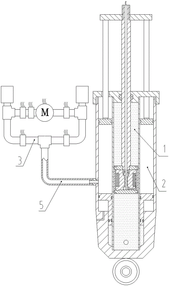
[0040] refer to figure 1 , The magneto-rheological strut with integrated air spring of the present invention is composed of three major parts, which are magneto-rheological shock absorber strut 1 , outer air spring 2 and air supply pressure regulating device 3 .

[0041] The magneto-rheological damper strut 1 is installed inside the outer air spring 2 and remains coaxial with the outer air spring 2 . The air supply pressure regulating device 3 is connected with the outer air spring 2 through an air supply hose 5 .

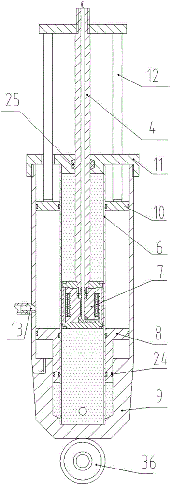
[0042] refer to figure 2 , this figure is a cross-sectional view of the front view of the magneto-rheological shock absorber strut 1 and the outer air spring 2; wherein, the shock absorber strut 1 is composed of the shock absorber damping force output rod 4, the shock absorber main piston 7, the shock absorber Vibrator working cylinder 6 is formed. The outer a...


PUM


Abstract

The invention discloses a magneto-rheological sliding column integrated with an air spring, and aims to solve the problem that damping force for compression stroke of a magneto-rheological damper is not provided sufficiently. The magneto-rheological sliding column consists of a magneto-rheological damper sliding column, an external air spring and an air supply pressure-regulating device, wherein the magneto-rheological damper sliding column is coaxially mounted inside the external air spring; and the air supply pressure-regulating device is connected to an external air spring pipeline. A damper main piston is in sliding seal fit with a damper working cylinder; the lower end of a damping force output rod is connected with the damper main piston; the upper part of the damping force output rod passes through a sliding column upper end cover and an air spring pressure plate, and is in sealing connection with the sliding column upper end cover and is in threaded connection with the air spring pressure plate; the sliding column upper end cover and an air spring housing are respectively fastened at upper and lower ends of the damper working cylinder; an air spring piston and a floating piston are sealed and mounted between the damper working cylinder and the air spring housing respectively; and the lower end of the air spring pressure plate passes through the sliding column upper end cover and is in contact with the upper end surface of the air spring piston.

Description

technical field [0001] The invention relates to a magneto-rheological sliding column, more precisely, the invention relates to a magneto-rheological sliding column integrated with an air spring, which is used in a vehicle suspension system. Background technique [0002] In the modern automobile structure, the suspension is an essential system of the vehicle, it is a necessary structure connecting the body and the wheels. Shock absorbers and springs are extremely important components that transmit and generate force in a suspension. Among them, the spring is responsible for alleviating the impact vibration of the road surface and improving the comfort of the vehicle, and the shock absorber is responsible for converting the vibration energy of the vehicle into heat energy for attenuation. Both of them play a vital role in improving the ride comfort of the vehicle. [0003] As a kind of suspension spring, air spring can freely adjust the vehicle height and spring height, which...

Claims


Application Information

Patent Timeline
Patent Type & Authority Applications(China)
IPC IPC(8): F16F9/06F16F9/53F16F9/43F16F9/32
CPCF16F9/062F16F9/063F16F9/067F16F9/3214F16F9/3235F16F9/43F16F9/535
Inventor 李静韩佐悦丁明慧周瑜张家旭
Owner JILIN UNIV
Why Eureka
Try Eureka