

Filling limiting cylinder valve
A bottling and valve core technology, applied in the field of cylinder valves, can solve the problems of increasing the movement resistance of the sealing ring, narrow opening area of the sealing ring, and limited air supply and inflation of the electromagnetic limiting bottle filling valve, so as to ensure reliability. and stability effects
- Summary
- Abstract
- Description
- Claims
- Application Information
AI Technical Summary
Problems solved by technology
Method used
Image

Examples
Embodiment Construction
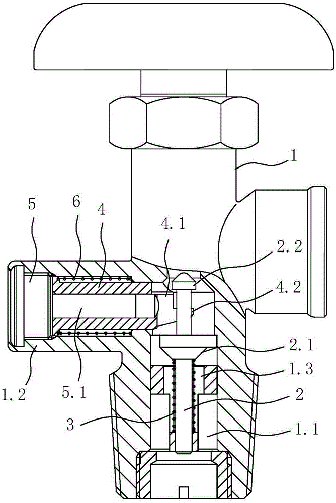
[0012] like figure 1 As shown, an electromagnetic limited filling bottle valve includes a valve body 1 with a flow channel 1.1, a valve core 2 capable of reciprocating axially in the flow channel 1.1 to open and close the flow channel 1.1, and a holding valve core 2 The first spring 3 that tends to move toward the direction of opening the flow channel 1.1, the sliding sleeve 4 that can move back and forth against the valve core 2 is installed in the clamping seat 1.2 on the side wall of the valve body 1, and is used to install the sliding sleeve 4 on the clamping joint. The screw plug 5 in the seat 1.2, the screw plug 5 is formed with an iron core 5.1 extending into the sliding sleeve 4, which can slide towards the valve core 2 by electromagnetically driving the sliding sleeve 4, and the outer sleeve of the sliding sleeve 4 is provided to keep it sliding away from the valve core 2 Trend of the second spring 6. In the present invention, a step hole 1.3 is formed in the flow ch...
PUM
 Abstract
Description
Claims
Application Information