Quick air-drying device for camshaft

A camshaft, fast technology, applied in heating devices, dryers for static materials, drying, etc., can solve the problems of low automation and complex structure, achieve high automation, reduce labor intensity, and improve work efficiency.

Inactive Publication Date: 2016-03-16
CHONGQING BENCHUANG MACHINERY CO LTD
View PDF0 Cites 6 Cited by
  • Summary
  • Abstract
  • Description
  • Claims
  • Application Information

AI Technical Summary

Problems solved by technology

[0005] In order to overcome the shortcomings of low degree of automation and complicated structure in the present invention for drying camshafts, the technical problem to be solved by the invention is to provide a special quick drying device for camshafts with high degree of automation and simple structure
Contents of the invention

Method used


Image

  • Quick air-drying device for camshaft
  • Quick air-drying device for camshaft
  • Quick air-drying device for camshaft

Examples


Embodiment 1

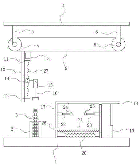
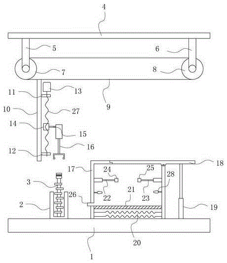
[0022] Both the left and right walls of the drying device 17 inboards are provided with fans 28 .

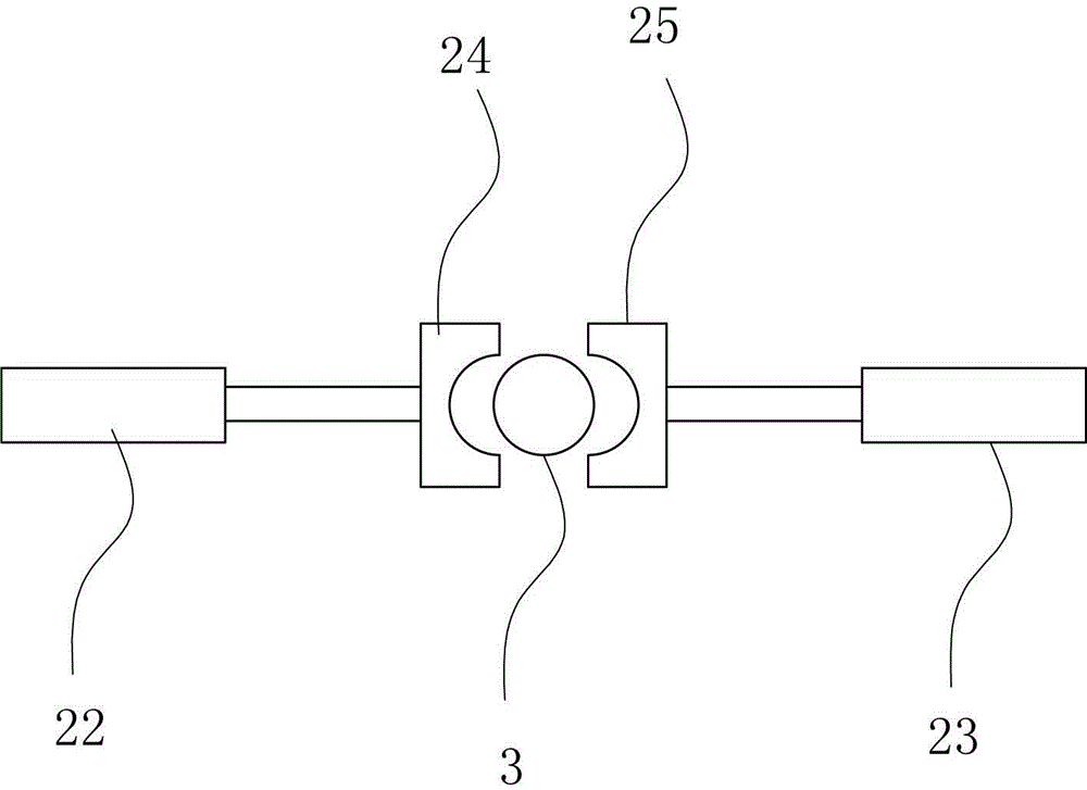
[0023] Base 1 right side lower end is provided with controller 29, and controller 29 is connected with electric gear 7, servomotor 13, thumb cylinder 16, extension cylinder 19, heating device 20, left cylinder 22, right cylinder 23 and blower fan 28 respectively.

[0024] Working principle: The worker puts the cleaned camshaft 3 into the rack 2, the servo motor 13 drives the screw 27 to reverse, the nut 14 moves downward on the screw 27, and the nut 14 drives the thumb cylinder 16 through the connecting rod III 15 Moving downward, when the thumb cylinder 16 pushes against the camshaft 3, the servo motor 13 stops rotating, the thumb cylinder 16 clamps the camshaft 3, the servo motor 13 drives the screw 27 to rotate forward, and the nut 14 moves upward on the screw 27 , the nut 14 drives the thumb cylinder 16 to move upward through the connecting rod Ⅲ15, the electric gear 7 rever...


PUM


Abstract

The invention belongs to the technical field of camshaft equipment, and particularly relates to a quick air-drying device special for a camshaft. According to the technical purposes, the quick air-drying device special for the camshaft is high in automation degree and simple in structure. In order to achieve the technical purposes, the quick air-drying device special for the camshaft comprises a base, a storage rack, the camshaft, a top plate, a connecting rod I, a connecting rod II, an electric gear, a driven gear, a conveying belt, a fixing plate, an upper bearing pedestal, a lower bearing pedestal, a servo motor, a nut, a screw rod, a connecting rod III, a thumb cylinder, an air-drying unit, a cover plate, a telescopic cylinder, a heating unit, absorbent paper, a left cylinder, a right cylinder, a left fixing clamping ring and a right fixing clamping ring. The defects that an existing camshaft air-drying device is low in automation degree and complex in structure are overcome through the quick air-drying device special for the camshaft, and the quick air-drying device special for the camshaft achieves the effects of being high in automation degree and simple in structure.

Description

technical field [0001] The invention belongs to the technical field of camshaft equipment, in particular to a special quick drying device for camshafts. Background technique [0002] camshaft is piston engine a part of it. Its function is to control the opening and closing of the valve. Although in four stroke engine The speed of the camshaft is crankshaft half of (in two stroke engine The middle camshaft rotates at the same speed as the crankshaft), but usually it is still very high and needs to withstand a lot of torque , so the design has high requirements on the strength and support of the camshaft, and its material is generally special cast iron, and occasionally forgings are used. Because the valve movement law is related to the power and running characteristics of an engine, the camshaft design plays a very important role in the engine design process. [0003] The current camshaft drying device has the disadvantages of low degree of automation, cumbersome o...

Claims


Application Information

Patent Timeline
Patent Type & Authority Applications(China)
IPC IPC(8): F26B9/04F26B23/00F26B25/00
Inventor 周勇
Owner CHONGQING BENCHUANG MACHINERY CO LTD
Why Eureka
Try Eureka