Collimator and inspection system

一种准直器、准直缝的技术,应用在扫描车辆的检查领域,达到提高图像质量、提高成像质量、增强能量的效果

Active Publication Date: 2016-03-16
TSINGHUA UNIV +1
View PDF7 Cites 15 Cited by
  • Summary
  • Abstract
  • Description
  • Claims
  • Application Information

AI Technical Summary

Problems solved by technology

The current inspection system is still unable to better resolve this contradiction

Method used


Image

  • Collimator and inspection system
  • Collimator and inspection system
  • Collimator and inspection system

Examples


no. 1 example

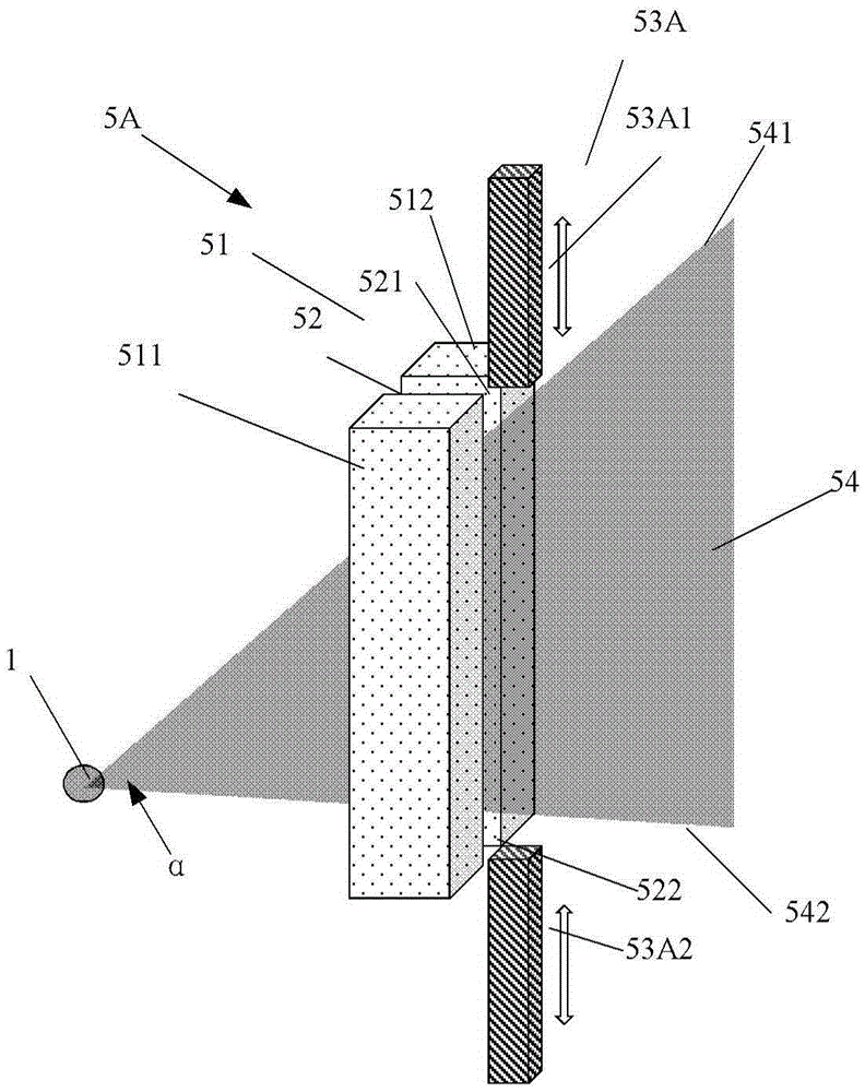
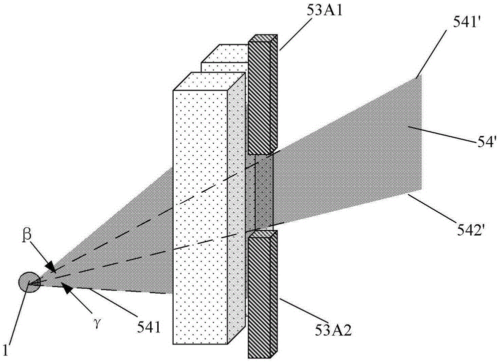
[0073] Figure 2A-2B A schematic diagram of a collimator 5A according to a first embodiment of the present invention is shown. As shown in the figure, the collimator 5A includes a collimator body 51, the collimator body 51 includes a first part 511 and a second part 512, and a collimating slit 52 is formed between the first part 511 and the second part 512, and the collimator body 51 includes a first part 511 and a second part 512. The straight slit 52 has a first end portion 521 and a second end portion 522 in its longitudinal direction; and a blocking member 53A, which can move relative to the collimator main body 51 to block at least a part of the collimating slit 52, so as to The included angle of the ray beam 54 emitted from the collimation slit 52 is changed, or the included angle and elevation angle of the ray beam 54 emitted from the collimated slit 52 are changed.

[0074] Specifically, such as Figure 2A-2B As shown, the shielding part 53A includes a first shieldin...

no. 2 example

[0077] Figure 3A-3D A schematic diagram of a collimator 5B according to a second embodiment of the invention is shown. In this embodiment, the same or similar components as those of the first embodiment are denoted by the same reference numerals. The difference between this second embodiment and the above-mentioned first embodiment mainly lies in the shielding member.

[0078] The collimator 5B includes a shielding member 53B. Specifically, such as Figure 3A As shown, the shielding part 53B includes a first shielding part 53B1 arranged on the side of the first part 511 of the collimator body 51 and a second shielding part 53B2 arranged on the side of the second part 512 of the collimator body 51, as shown in FIG. As shown, both the first shielding part 53B1 and the second shielding part 53B2 have a multi-level stepped structure. In this way, when the first shielding member 53B1 and the second shielding member 53B2 can move left and right in the Z plane relative to the co...

no. 3 example

[0081] Figures 4A-4DA schematic diagram of a collimator 5C according to a third embodiment of the present invention is shown. In this embodiment, components identical or similar to those in the first and second embodiments are denoted by the same reference numerals. This third embodiment differs from the above-mentioned second embodiment mainly in the shape of the shielding member. This collimator 5B includes a shielding member 53C. Such as Figures 4A-4D As mentioned above, the shielding part 53C includes a first shielding part 53C1 disposed on the side of the first part 511 of the collimator body 51 and a second shielding part 53C2 disposed on the side of the second part 512 of the collimator body 51. The multi-level steps in the second embodiment are different, and both the first shielding part 53C1 and the second shielding part 53C2 have a triangular cross-sectional shape. In this way, when the first shielding part 53C1 and the second shielding part 53C2 move left and...


PUM


Abstract

The invention discloses a collimator and an inspection system having the collimator. The collimator comprises: a collimator main body, wherein the collimator main body comprises a first portion and a second portion, a collimating slit is formed between the first portion and the second portion, and the collimating slit is provided with a first end portion and a second end portion in the vertical direction of the collimating slit; and a shielding part, wherein the shielding part can move relative to the collimator main body to make the included angle and the elevation angle of ray beams emitted from the collimating slit change. The invention also discloses the inspection system having the collimator and used for scanning a vehicle, and an inspection method for scanning the vehicle.

Description

technical field [0001] The invention relates to an adjustable collimator and an inspection system, in particular, to an inspection system for scanning a vehicle and an inspection method for scanning a vehicle. Background technique [0002] The inspection system generally inspects the object to be inspected by X-rays and other rays. When using such an inspection system, it is generally necessary to ensure the image quality of the imaging while controlling or monitoring the dose rate of the external radiation, ie the boundary. [0003] In the current inspection system, when the area of ​​the radiation protection device and the radiation control area remain unchanged, the method of increasing the dose rate is used to improve the image quality of the imaging, and the dose rate of the boundary will inevitably be increased at this time; or, in order to control The dose rate of the boundary has to sacrifice the image quality of the imaging. It can be seen that improving the image...

Claims


Application Information

Patent Timeline
Patent Type & Authority Applications(China)
IPC IPC(8): G01N23/04
CPCG01N23/04G01N2223/3301G01N2223/3302G01N2223/03G01N2223/316G01N2223/1013G01N2223/1016G01N2223/106G01N2223/66G21K1/04G01V5/22G21K1/043
Inventor 康克军李营李荐民李玉兰朱国平
Owner TSINGHUA UNIV
Why Eureka
Try Eureka