Supercharge Your Innovation With Domain-Expert AI Agents!

Power Detector And Associated Method For Eliminating The Difference Of I-v Phase Difference Between Transmission Path And Detection Path

A detector and power amplifier technology, applied in the field of power detection, can solve the problems of inability to track the phase difference θ, inability to track the output power, etc., and achieve the effect of reducing the impact

Inactive Publication Date: 2016-03-16
MEDIATEK INC
View PDF3 Cites 0 Cited by
  • Summary
  • Abstract
  • Description
  • Claims
  • Application Information

AI Technical Summary

Problems solved by technology

If the phase delay is too large, then the detected power P det will not follow the output power P o , resulting in the inability to track the phase difference θ
Therefore, the detected power P det will not be able to track the output power P o change, the output power P o The variation of is caused by the non-ideal antenna

Method used


Image

  • Power Detector And Associated Method For Eliminating The Difference Of I-v Phase Difference Between Transmission Path And Detection Path
  • Power Detector And Associated Method For Eliminating The Difference Of I-v Phase Difference Between Transmission Path And Detection Path
  • Power Detector And Associated Method For Eliminating The Difference Of I-v Phase Difference Between Transmission Path And Detection Path

Examples


Embodiment Construction

[0047] In order to make the technical problems, technical solutions and beneficial effects solved by the present invention clearer, the following further describes the present invention in detail with reference to the accompanying drawings and embodiments. It should be understood that the specific embodiments described herein are only used to explain the present invention, but not to limit the present invention.

[0048] Certain words are used in the description and claims of this application to refer to specific components. Those skilled in the art should understand that although hardware manufacturers may use different terms to refer to the same component, this specification and claims do not distinguish components by name differences, but use differences in components as The criterion of distinction. The "including", "including" and other similar terms mentioned in the entire specification and claims are all open-ended terms, so they should be interpreted as "including but no...


PUM


Abstract

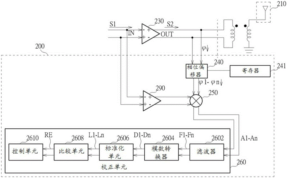
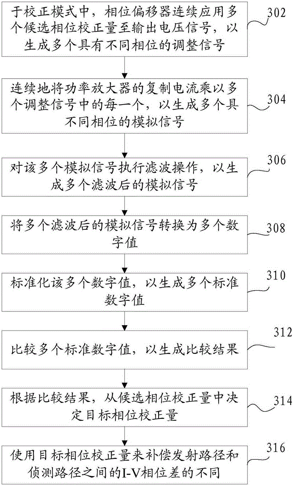
A power detector for detecting an output power of a power amplifier is provided. The power amplifier is used to transmit signal power to the antenna. The power detector includes a phase shifter, a multiplier and a calibration unit. The phase shifter sequentially applies a plurality of candidate phase calibration amounts to the output voltage of the power amplifier to generate a plurality of adjusted signals with different phases in a calibration mode. The multiplier sequentially mixes the replica current and each of the plurality of adjusted signals, to generate a plurality of analog signals with different phases. The calibration circuit determines a target phase calibration amount of the phase shifter from the candidate phase calibration amounts according to the plurality of analog signals.

Description

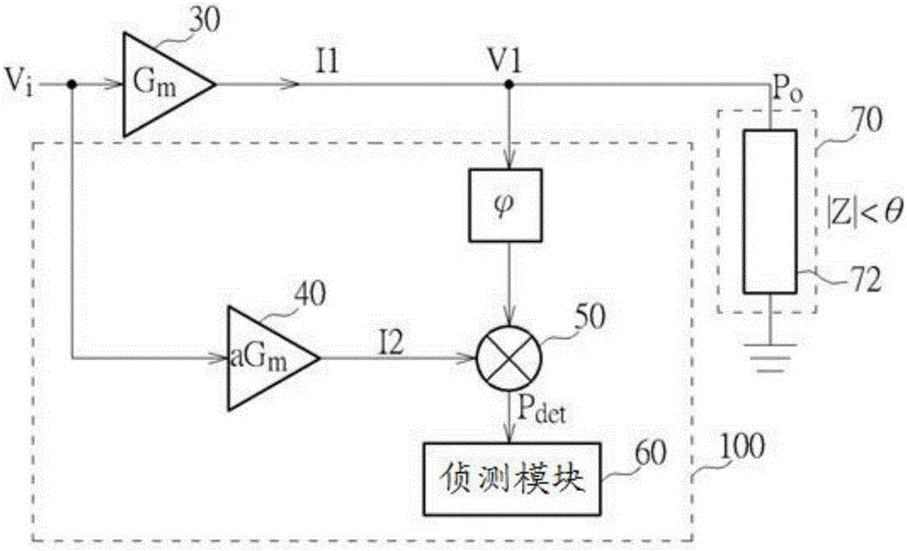
Technical field [0001] The present invention relates to the field of power detection technology, in particular to a power detector and a method for eliminating the I-V phase difference between the transmission and detection paths. Background technique [0002] The power detector is used to perform TSSI (transmission signal strength indication) operation, so as to perform transmission power compensation. The power detector needs to be insensitive to changes in the output impedance of the transmitter. Please refer to figure 1 , Is a schematic structural diagram of a conventional power detector 100 for detecting the output power of the power amplifier 30. The power detector 100 includes a power amplifier replica 40, a multiplier 50, and a detection module 60. The power amplifier 30 amplifies the input voltage Vi and outputs the amplified current I1. The power amplifier copy unit 40 receives the same input voltage Vi and outputs the detected copy current I2, where I1=Gm*Vi, I2=a*Gm...

Claims


Application Information

Patent Timeline
Patent Type & Authority Applications(China)
IPC IPC(8): H04B17/318H04B1/04
CPCH04B17/0085H04B17/102H04B17/104H04B17/13H04B17/14H04B17/16H04B17/19G01R21/133H03F3/21
Inventor 张伯宇
Owner MEDIATEK INC
Features
  • R&D
  • Intellectual Property
  • Life Sciences
  • Materials
  • Tech Scout
  • Unparalleled Data Quality
  • Higher Quality Content
  • 60% Fewer Hallucinations
Learn More