Multicast resource distribution and transmission method for scalable video in system with multiple base stations

A technology of resource allocation and transmission method, applied in the field of multicast resource allocation and transmission, can solve the problems of multi-base station system not getting too much research, data transmission interference, etc., to achieve good video service quality, improve video quality, and increase capacity Effect

Active Publication Date: 2016-03-16
HEFEI UNIV OF TECH
2 Cites 12 Cited by

AI-Extracted Technical Summary

Problems solved by technology

[0009] However, all the above studies on multi-base station cooperative systems are only for transmission under multi-base station and multi-cell, that is, only one base station exists in the same area, and multiple base stations cooperate in multiple cells, and different base stations use the same frequency band resource , and there will be da...

Abstract

The invention discloses a multicast resource distribution and transmission method for a scalable video in a system with multiple base stations. The multicast resource distribution and transmission method is characterized by comprising the following steps that: (1), mobile equipment in one cellular cell receives data transmitted from different base stations; (2), a video flow is divided into a base layer and an enhancement layer; (3), a base station control centre selects one proper transmission base station for each video layer and determines which modulation coding manners are used; and (4), the multiple base stations transmit the video layers according to the appointed modulation coding manners and calculate the total number of the video layers received by the mobile equipment in the system and the utility value of the system. According to the invention, spectrum resources are effectively utilized; the utility value of the whole system is increased; the overall throughput of a network environment is effectively increased; and thus, the better video service quality is provided for users.

Application Domain

Site diversitySource coding adaptation +5

Technology Topic

Computing systemsResource distribution +7

Image

  • Multicast resource distribution and transmission method for scalable video in system with multiple base stations
  • Multicast resource distribution and transmission method for scalable video in system with multiple base stations
  • Multicast resource distribution and transmission method for scalable video in system with multiple base stations

Examples

  • Experimental program(1)

Example Embodiment

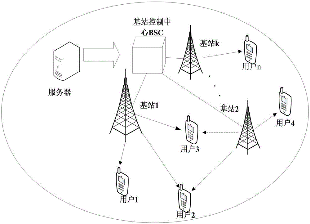
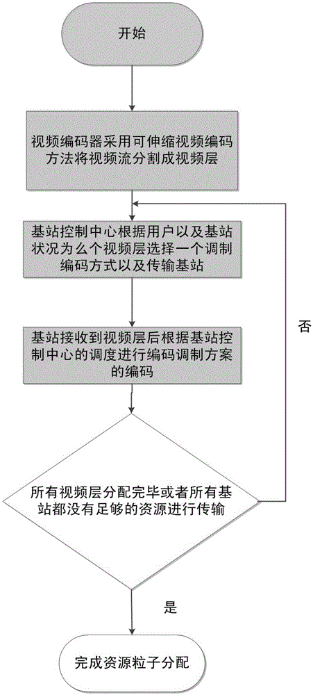
[0042] In this embodiment, a multicast resource allocation and transmission method for scalable video in a multi-base station system is a resource allocation scheme for data transmission in a multi-base station system, such as figure 1 As shown, the multi-base station system consists of a server, a base station control center BSC, K base stations, N s The server is directly connected to the base station control center, and transmits data to the base station control center through a reliable link. The resource allocation of broadcast, from the low layer to the high layer, designate a base station that covers the user to the maximum extent as the transmission base station of the video layer, and select the appropriate modulation and coding method for each video layer, until all video layers are transmitted or all base stations are completed. There are not enough resource particles to transmit a video layer so far. Resource particle refers to the smallest resource allocation unit in the system, which can refer to the time domain, frequency domain of the system bandwidth, or a combination of time domain and frequency domain; in a multi-base station system, K base stations use different frequency bands, and The kth base station contains T k The number of resource particles; 1≤k≤K; the i-th mobile device can receive video data transmitted from any base station; 1≤i≤N s; Suppose K base stations want to transmit a video stream s to N s mobile devices, such as figure 2 As shown, the base station control center BSC performs the allocation of resource elements in a video stream s and the transmission of the video stream s according to the following steps:
[0043] Step 1. The video encoder in the server divides the video stream s into L+1 video layers composed of a base layer and L enhancement layers, and transmits them to the base station control center BSC through an optical fiber; let L+1 video layers The transmission rate of the l-th video layer is λ l;
[0044] Assuming that there is a base station control center and three base stations in the network environment, the frequency bands of the three base stations are selected at 2.5G, 2G and 888M respectively, and the corresponding resource particles of the three base stations are 40(A), 30(B) and 20M(C), the transmit power is 46dBm, 43dBm and 33dBm respectively, 100 mobile users are randomly distributed in the annular area 350 to 1000 meters away from the base station, the antenna gain and noise figure are 17dB and 5dB, the path loss in the network environment The model is: PL(dB)=35.2+35log 10 d, where d is the distance between the user and the base station, in meters, the modulation and coding scheme that can be decoded by each user can be calculated through the model, and for different users, he can receive data transmitted from different base stations; the server The video encoder uses the scalable video coding method to divide a video stream into a base layer and 5 enhancement layers, which are transmitted to the base station control center through optical fibers; and there is a dependency between each video layer, and any layer has not been moved. If the device decodes correctly, then all video layers above this layer are invalid to the device, even though the mobile device can receive this layer and cannot decode it correctly. That is to say, only after all the 1st to 1-1th video layers are received by the mobile device and decoded correctly, the video layer 1 is valid for the device; in this model, it is assumed that the base station transmits the 6-layer video layer in the The fixed rate of each video layer is 64Kbps;
[0045] Step 2. Let the modulation and coding mode of the base station control center BSC be MCS={MCS 1 ,MCS 2 ,...,MCS m ,...,MCS M};MCS m Indicates the mth modulation and coding mode; the M modulation and coding modes MCS are arranged in descending order of the number of resource particles consumed; 1≤m≤M;
[0046] In this embodiment, it is assumed that the modulation and coding scheme MCS available in the system m A total of 6 species, recorded as {MCS 1 ,MCS 2 ,...,MCS 6}, as shown in Table 1, the larger the index value of the MCS, that is, the higher the level of modulation and coding, the greater the rate of data transmission per unit resource particle can be, and the less resource particles are consumed at a fixed layer rate, but The higher the signal-to-noise ratio requirement for the user, the better the link quality of the device, the higher the level of modulation and coding methods that can be supported, and the better the quality of video service he can get;
[0047] Table 1 Comparison of parameters of different MCS
[0048] M
[0049] Step 3, the base station control center BSC according to N s According to the channel conditions of the mobile devices and the instantaneous resource conditions of the K base stations, the greedy algorithm is used to select the corresponding modulation and coding mode for the lth video layer and the base station that transmits the lth video layer; thus assigning corresponding modulation and coding methods to L+1 video layers and the base station to be transmitted; complete the allocation of resource elements in a video stream s;
[0050] In this embodiment, the base station control center BSC uses a greedy algorithm to select an appropriate transmission base station and modulation and coding mode for each video layer. The result of the selection of the greedy algorithm is to select the appropriate transmission base station for each layer and assign the appropriate modulation and coding method from the base layer of the video layer. layer transmission base station, and select a modulation and coding method that can increase the utility value of the system as the modulation and coding method of this layer; and specify that the first video layer of a video stream uses MCS m For modulation and coding, if the l+1th layer of the video stream is transmitted, the modulation and coding level used must be greater than the modulation and coding method used for the transmission of the lth layer of video layer. Specifically, the greedy algorithm in step 3 is based on Proceed as follows:
[0051] Step 3.1, initialize l=1;
[0052] Step 3.2, initialize m=1;
[0053] Step 3.3, the base station control center BSC selects the base station that covers the largest number of mobile devices as the transmission base station of the lth video layer according to the number of mobile devices covered by the K base stations, which is denoted as the max. l a transmission base station;
[0054] In one frame of the network environment, the number of resource particles allocated by the three base stations are 40(A), 30(B) and 20(C) respectively. The greedy algorithm is used to start from the base layer of the video stream for each device of the device. Select a suitable transmission base station for the video layer. From the instantaneous status of users in Table 2, it can be known that the base station that can maximize the number of users receiving this layer is base station A, and then base station A is selected as the transmission base station of this layer;
[0055] Table 2 Instantaneous status of system users when the base station transmits in a state
[0056] Base station type
[0057] Step 3.4, use formula (1) to calculate the lth video layer and use the mth modulation and coding mode MCS m The number of resource particles consumed τ l,m :
[0058] τ l,m =λ l /β m (1)
[0059] In formula (1), β m Indicates that the mth modulation and coding method MCS is used m The transmission rate that a single resource particle can bear;
[0060] Step 3.5, compare the max l The number of resource particles T of each transmission base station maxl More than or equal to the lth video layer uses the mth modulation and coding method MCS m The number of resource particles consumed τ l,m Whether it is established, if it is established, it means the max. l The transmission base stations can use the mth modulation and coding scheme MCSm Carry out the transmission of the lth video layer, and execute step 3.6; otherwise, assign m+1 to m, and return to step 3.4 to execute sequentially until m=M;
[0061] Starting from the bottom layer of the video stream, for the base layer, the modulation and coding method that can best increase the value of the system utility function is MCS 1 , the base station control center will select MCS 1 As the modulation and coding method of this layer; because base station A is the transmission base station of this layer, when base station A uses MCS 1 When transmitting this layer, the transmission rate that a single resource element can achieve in the first modulation and coding method is 4.8Kbps, and the required user signal-to-noise ratio is 3.716dB. In this stage, the base station A consumes the amount of energy when transmitting this layer. The number of resource particles is τ l,m =[λ l /β m ]=[64Kbps/4.8Kbps]=14; the number of resource particles remaining in base station A is T A -τ l,m =40-14=26;
[0062] Step 3.6, put T maxl -τ l,m assign to T maxl , thus updating the max l The number of resource particles of each transmission base station;
[0063] Step 3.7, assign l+1 to l, and return to step 3.3 to execute sequentially until l=L;
[0064] When the resource allocation scheme is selected for the second layer of the video stream, Table 3 shows the user status that the three base stations transmit the layer and can receive the layer, then the base station control center BSC selects the base station B as the transmission base station for the layer; Greedy criterion, the modulation and coding method allocated by the greedy algorithm for the second video layer of the video layer is the second modulation and coding method MCS 2 , if base station B selects MCS 2 When transmitting the second video layer, the second modulation and coding method MCS 2 The transmission rate that a single resource particle can achieve is 7.2Kbps, and the required signal-to-noise ratio is 5.947dB, so the number of resource particles consumed by base station B to transmit the video layer is τ l,m =[λ l /β m ]=[64Kbps/7.2Kbps]=9; and the remaining T B -τ l,m =30-9=21 resource elements; according to the above allocation, until the transmission of 6 video layers is completed, it means that the base station completes the allocation of all video layer resource elements in a frame, or until the remaining resource elements of the three base stations cannot be Each video layer selects a suitable modulation and coding scheme;
[0065] Table 3 Transient status of system users when the base station transmits in another state
[0066] Base station type
[0067] Step 4. According to the modulation and coding modes allocated by each of the K base stations, according to the transmission rate of each video layer, and by consuming a certain number of resource particles, to N s Each mobile device transmits the corresponding video layer; completes the transmission of a video stream s;
[0068] In the previous step, the base station control center BSC selects a suitable transmission base station and modulation and coding method for each video layer according to the channel conditions of the entire system users and the resource particles of the three base stations. When the transmission scheme of the video layer is formulated, the base station control center BSC The video layer is transmitted to a specific base station, and after receiving the video layer, the base station encodes it in the specified modulation and coding mode, and transmits it to the system user through the wireless link according to the required transmission rate;
[0069] Step 5. Use formula (2) to calculate N s The sum of the utility values ​​of the mobile devices, U:
[0070] Objective function: U = Σ i = 1 N s U ( r i ) - - - ( 2 )
[0071] Restrictions: Σ m = 1 M ζ l , m ≤ 1 - - - ( 3 )
[0072] Σ k = 1 K γ l k ≤ 1 - - - ( 4 )
[0073] Σ m = 1 M Σ l = 1 L γ l k ζ l , m τ l , m ≤ T k - - - ( 5 )
[0074] Formula (2) represents N s The cumulative utility function value of a mobile device; in formula (2), r i Represents the cumulative rate of the i-th mobile device; U(r i ) represents the utility function value of the ith mobile device;
[0075] Equation (3) indicates that each video layer can only select one modulation and coding method for transmission; in Equation (3), ζ l,m is the coding indicator function, indicating that when the l-th video layer uses the m-th modulation and coding mode MCS m When transmitting, the encoding indicates the function ζ l,m is 1, otherwise, the coding indicates the function ζ l,m is 0;
[0076] Equation (4) indicates that each video layer can only be transmitted by one base station; in Equation (4), is the transmission indicator function, indicating that when the l-th video layer of the video stream is transmitted by the k-th base station, the transmission indicator function is 1, otherwise, the transfer indicator function is 0;
[0077] Equation (5) indicates that the number of resource particles consumed by each base station for transmitting the video layer cannot be more than the number of resource particles owned by each base station itself; in formula (5), τ l,m Indicates that the lth video layer is at the transmission rate λ l Use the mth modulation and coding method MCS m The number of resource particles consumed during modulation coding.
[0078] Assume that the system utility function is a non-negative and non-decreasing function log that has a positive correlation with the user's reception rate r 10 r, and the user's receiving rate is cumulative. For example, as mentioned above, the layer rate of one video layer is 64Kbps. If a user effectively receives two video layers, his receiving rate is 128Kbps. According to the characteristics of scalable video coding It can be seen that if the mobile user wants to decode the video layer 1, he must correctly decode the previous layers 1 to 1-1; from the previous steps, we can see that the video layers that the system can effectively transmit are a base layer and 4 enhancement layers. The fixed rate of each layer is 64Kbps, and the value is substituted into the formula (2), the final value of the system utility function in the network environment is: 741.8, which represents the data throughput of the entire network environment.

PUM

no PUM

Description & Claims & Application Information

We can also present the details of the Description, Claims and Application information to help users get a comprehensive understanding of the technical details of the patent, such as background art, summary of invention, brief description of drawings, description of embodiments, and other original content. On the other hand, users can also determine the specific scope of protection of the technology through the list of claims; as well as understand the changes in the life cycle of the technology with the presentation of the patent timeline. Login to view more.

Similar technology patents

Display and storage system

InactiveUS6129222Aincrease capacityreduce clutter
Owner:BURNES HOME ACCENTS +1

Foot-operated computer input device

ActiveUS20100001948A1increase capacity
Owner:BECKMER PRODS

Preparation method of magnesium-doped lithium nickel cobalt oxide anode material for lithium ion battery

ActiveCN102412389AUniform particle distributionincrease capacity
Owner:HENGDIAN GRP DMEGC MAGNETICS CO LTD

Classification and recommendation of technical efficacy words

  • increase capacity

Wireless communal gaming system

InactiveUS20080096659A1increase capacityreduce and eliminate need
Owner:SHUFFLE MASTER

Interference control in CDMA networks

InactiveUS20060068849A1decrease interferenceincrease capacity
Owner:LUCENT TECH INC

Virtual antenna array

ActiveUS7594010B2increase capacity
Owner:KING'S COLLEGE LONDON

Multi-frequency antenna with dual loops

ActiveUS20070285321A1increase capacity
Owner:ADVANCED CONNECTEK INC
Why Eureka
Try Eureka