Die tool of small pack basket heating radiator

A radiator and back basket technology is applied in the field of civil radiator processing and manufacturing, which can solve the problems of weak welding, infiltration of heat conduction medium, and erosion of weld seams, and achieve the effect of saving material and labor costs, reliable service life and good market prospects.

Active Publication Date: 2016-03-23
ZAOZHUANG FUYUAN ENVIRONMENTAL PROTECTION & ENERGY SAVING MACHINERY MFG CO LTD
View PDF7 Cites 0 Cited by
  • Summary
  • Abstract
  • Description
  • Claims
  • Application Information

AI Technical Summary

Problems solved by technology

The main components of the above-mentioned mold tooling are only used for the welding and forming of the profiles used in the small pantry heating radiator. In this through-connection mode, the welds are all on the outer surface, which affects the appearance of the product. When the welding temperature is unstable, especially For thin-walled stainless steel materials, it is very easy to cause weak welding or breakdown, and at the same time, the heat-conducting medium will penetrate into the gap between the annular flange of the connecting pipe and the row pipe, which may corrode the weld; in a known stainless steel In the prior art of welded radiators, the connecting pipe is provided with an outwardly protruding annular flange, and the row pipe to be connected is inserted and welded outside the ring flange of the connecting pipe, or the row pipe to be connected is inserted into the The mold tooling installed and welded in the annular flange of the connecting pipe, the row pipes in this prior art are all arranged in the same plane between the two connecting pipes, and it is impossible to realize the non-identical The mold tooling for the through connection of the bent horizontal pipe and the vertical connecting pipe on the plane

Method used


Image

  • Die tool of small pack basket heating radiator
  • Die tool of small pack basket heating radiator
  • Die tool of small pack basket heating radiator

Examples


Embodiment Construction

[0016] The present invention will be described in further detail below in conjunction with the accompanying drawings and embodiments.

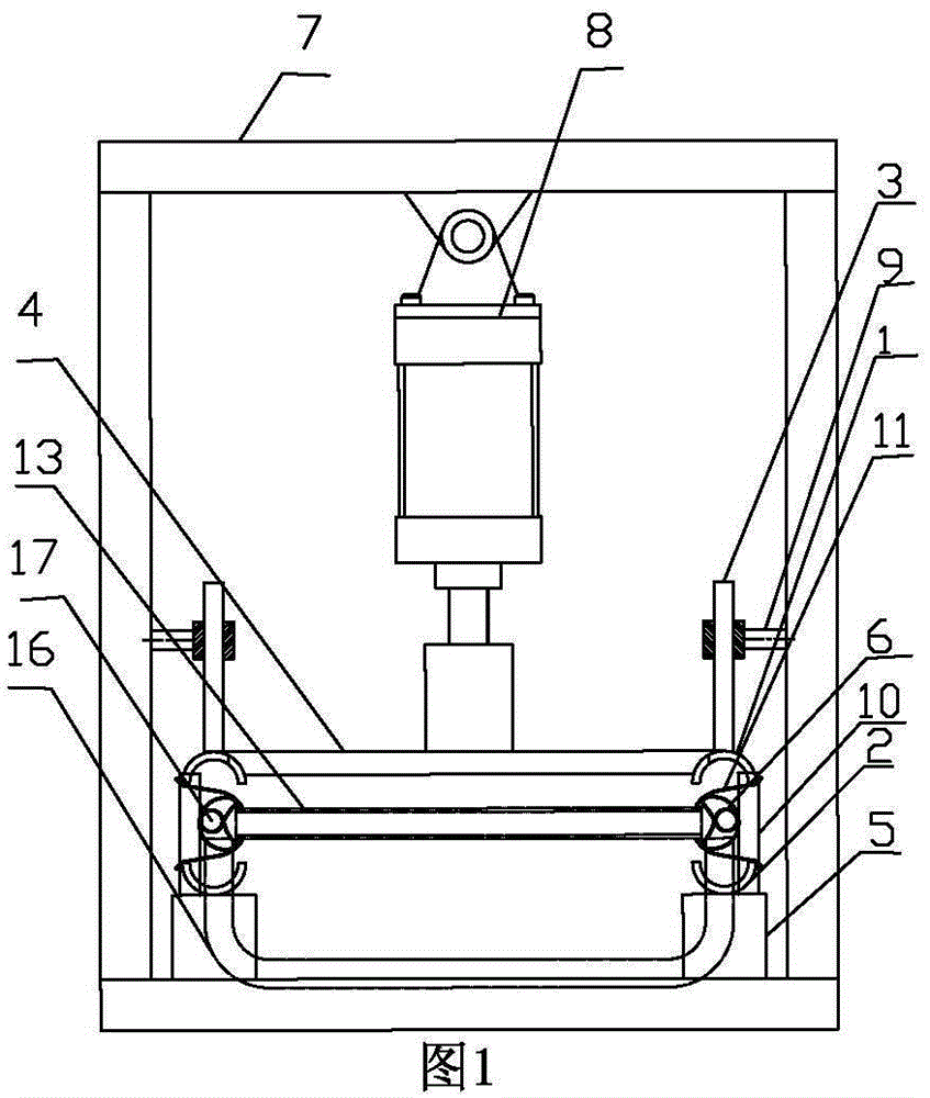
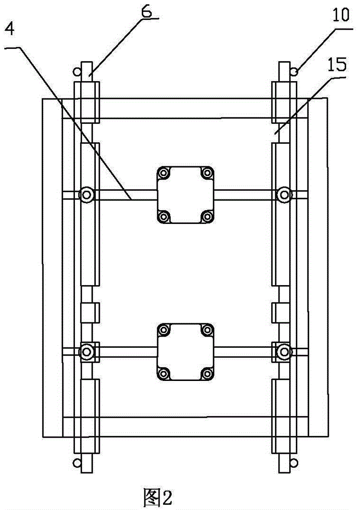
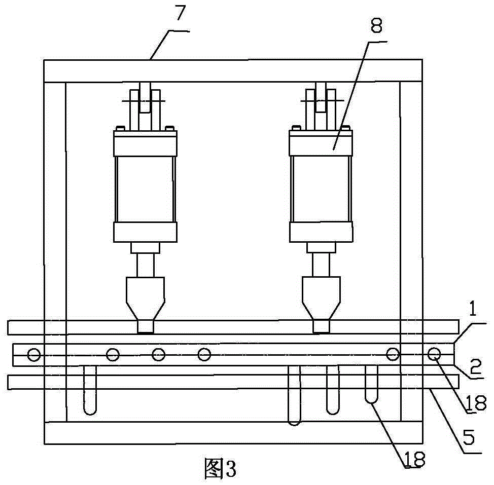
[0017] Such as figure 1 , figure 2 , image 3 , Figure 4 Shown:

[0018] The mold tooling of the small basket type heating radiator, which includes two pairs of pressure tube arc plate joints arranged symmetrically from left to right, and the pressure tube arc plate joints include upper arc plate 1, lower arc plate 2, and guide rod shaft 3 , support plate 4, seat cushion 5, each pair of pressure tube arc plates is combined by upper arc plate 1, lower arc plate 2, and inner core tube 6, and also includes frame 7, cylinder 8, guide rod bushing 9, Positioning shaft 10, one end of cylinder 8 is connected with frame 7, the other end of cylinder 8 is connected with support plate 4, guide rod sleeve 9 is fixed on both sides of frame 7, the upper end of seat cushion 5 is connected with lower arc plate 2, and the lower end of seat cushion 5 Conn...


PUM


Abstract

The invention belongs to the technical field of civil radiator processing and manufacturing, and discloses a stainless steel welding structure member die tool of a small pack basket heating radiator. Inner core pipes are respectively placed in two vertical communicating pipes. A concave arc surface of the inner core pipe contacts with two end faces of a straight horizontal pipe. The left side of the inner core pipe is in an annular arc-shaped surface, and contacts with two edges of the profiles of the two vertical communicating pipes when being extruded and closed, and under the action of a pressure strut of a cylinder, the inner core pipe and the two edges of the profiles of the two vertical communicating pipes move relatively to clamp, so that the two edges of the profiles of the two vertical communicating pipes are kneaded tightly. A moon shape in the inner core pipe is divided into a plurality of sections. A space distance is between the end faces of the sections. The end faces on two ends of a bended horizontal pipe are inserted into the space distance. A cylindrical pipe is arranged on the upper part of the middle position of the moon shape of the inner core pipe. The bottom of the cylindrical pipe contacts with two end faces of the bended horizontal pipe. When the pressure strut of the cylinder contracts and exits, the inner core pipes on the two ends respectively rotate inward for 90 DEG, and the inner core pipes are pulled out.

Description

technical field [0001] The invention belongs to the technical field of processing and manufacturing of civil radiators, and relates to a mold tooling for a stainless steel welding component of a pantry-type heating radiator, in particular to a mold tooling for a pantry-type heating radiator made of thin-walled stainless steel. . Background technique [0002] The common main structure of the mold tooling of the small basket type heating radiator is: a frame is placed with two vertical connecting pipes symmetrically arranged left and right, a number of straight horizontal pipes arranged up and down and distributed on the same vertical plane, and the straight horizontal pipes The two ends are respectively connected with two vertical connecting pipes, and it also includes a plurality of bent horizontal pipes with bends at both ends that are not on the same vertical plane as the straight horizontal pipes. Two vertical connecting pipes are connected through each other so that the...

Claims


Application Information

Patent Timeline
Patent Type & Authority Applications(China)
IPC IPC(8): B23K37/053B23K101/14
CPCB23K37/053B23K2101/14
Inventor 孙有福崔淼孙淑慧
Owner ZAOZHUANG FUYUAN ENVIRONMENTAL PROTECTION & ENERGY SAVING MACHINERY MFG CO LTD
Why Eureka
Try Eureka