MVR (Mechanical Vapor Recompression) multiple effect evaporator

A multi-effect evaporator and three-effect evaporator technology, applied in the field of evaporators, can solve the problems of poor heating effect, noise of MVR compressor, low utilization rate of MVR compressor, etc.

Pending Publication Date: 2018-03-06
叶春穗
View PDF5 Cites 3 Cited by
  • Summary
  • Abstract
  • Description
  • Claims
  • Application Information

AI Technical Summary

Problems solved by technology

[0002] At present, most of the multi-effect evaporators on the market use the same type of evaporator. The first-effect evaporator uses fresh steam, and the rest of the evaporators use the secondary steam discharged from the first-effect evaporator. The temperature of the secondary steam gradually decreases, resulting in a heating effect. Poor, low heating efficiency, and most MVR evaporators adopt single-effect form, the utilization rate of the MVR compressor is low, and the MVR compressor will generate noise and emit a lot of heat during operation. In addition, most circulating pumps use high-power electric Only the circulation pump can meet the requirements of forced liquid circulation, which makes the energy consumption too high and the circulation pump is easy to block

Method used


Image

  • MVR (Mechanical Vapor Recompression) multiple effect evaporator
  • MVR (Mechanical Vapor Recompression) multiple effect evaporator
  • MVR (Mechanical Vapor Recompression) multiple effect evaporator

Examples


Embodiment Construction

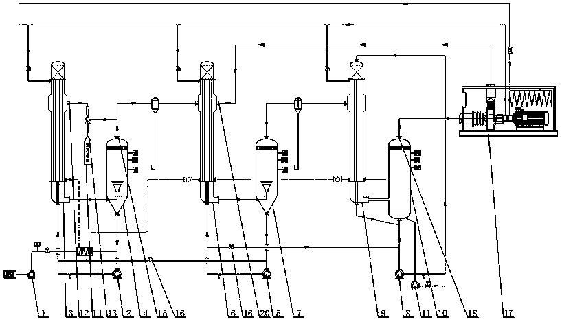
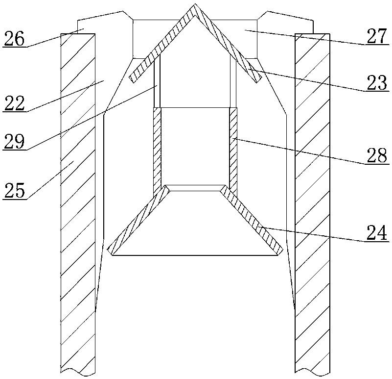
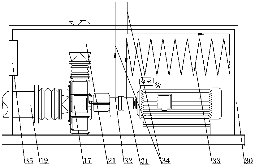
[0015] refer to figure 1 , figure 2 and image 3 As shown, the MVR multi-effect evaporator provided by the present invention comprises a feed pump 1, a first-effect forced circulation pump 2, a first-effect evaporator 3, a first-effect separator 4, a second-effect forced circulation pump 5, a second-effect forced circulation pump 5, Evaporator 6, two-effect separator 7, three-effect forced circulation pump 8, three-effect evaporator 9, three-effect separator 10, discharge pump 11, the steam port 12 of the first-effect evaporator 3 is connected with a heat pump 13, and the heat pump The other end of 13 is the steam inlet 14, the steam ports 12 of the other effect evaporators are sequentially connected to the steam outlet 15 at the top of the previous effect separator, the bottom outlet of each effect separator is connected to the corresponding forced circulation pump of each effect, and the first effect forced circulation The pump 2 can be connected to the two-effect forced ...


PUM


Abstract

The invention discloses an MVR (Mechanical Vapor Recompression) multiple effect evaporator which comprises a feed pump, a single-effect forced circulation pump, a single-effect evaporator, a single-effect separator, a two-effect forced circulation pump, a two-effect evaporator, a two-effect separator, a three-effect forced circulation pump, a three-effect evaporator, a three-effect separator and adischarge pump connected in sequence by virtue of pipelines, wherein a steam port of the single-effect evaporator is connected with a heat pump; a steam inlet is formed in the other end of the heat pump; steam ports of the rest each-effect evaporators are sequentially connected to the steam outlet in the top of the last-effect separator; the bottom outlet of each-effect separator is connected with a corresponding each-effect forced circulation pump; the single-effect forced circulation pump can be communicated with the two-effect forced circulation pump by virtue of a valve; the two-effect forced circulation pump can be communicated with the three-effect forced circulation pump by virtue of a valve; the bottom of the three-effect evaporator is connected with the inlet of the discharge pump; the three-effect evaporator is a falling-film evaporator; and an MVR compressor is arranged between the three-effect separator and the two-effect evaporator. According to the MVR multiple effect evaporator, the steam utilization rate is high, so that the steam consumption is reduced, the membrane distribution effect is excellent, the noise is low, the heat dissipation performance is excellent,and the energy consumption is low.

Description

technical field [0001] The invention relates to an evaporator, in particular to an MVR multi-effect evaporator. Background technique [0002] At present, most of the multi-effect evaporators available on the market use the same type of evaporator. The first-effect evaporator uses fresh steam, and the other evaporators use the secondary steam discharged from the first-effect evaporator. The temperature of the secondary steam gradually decreases, resulting in a heating effect. Poor, low heating efficiency, and MVR evaporators mostly use single-effect form, the utilization rate of the MVR compressor is low, and the MVR compressor will generate noise and emit a lot of heat during operation. In addition, most of the circulating pumps use high-power electric motors. Only the circulating pump can meet the requirements of forced liquid circulation, which makes the energy consumption too high and the circulating pump is easy to block. SUMMARY OF THE INVENTION [0003] In view of t...

Claims


Application Information

Patent Timeline
Patent Type & Authority Applications(China)
IPC IPC(8): B01D1/26B01D1/30
CPCB01D1/26B01D1/30
Inventor 叶春穗
Owner 叶春穗
Why Eureka
Try Eureka