Vertical tube type falling-film evaporator

A technology for falling film evaporators and standpipes, applied in vertical pipe evaporators, evaporation, general water supply saving, etc., can solve problems such as high steam operating costs, increased burden on enterprises, poor liquid film formation effect, etc., to achieve increased The effect of large heat transfer driving force and evaporation efficiency, low operating cost and high recovery rate

Active Publication Date: 2016-12-07
LUOYANG SUNRUI SPECIAL EQUIP
View PDF5 Cites 18 Cited by
  • Summary
  • Abstract
  • Description
  • Claims
  • Application Information

AI Technical Summary

Problems solved by technology

The equipment often has shortcomings such as poor liquid film formation effect and low liquid film stability, which affect heat transfer efficiency; steam and film-like liquid flowing down are discharged from the lower part of the heat exchange tube together, and the stripping effect of steam is not fully utilized; In addition, the heat source of evaporation and concentration operation mainly adopts the continuous boiler steam
For materials with low concentration and large processing capacity, the energy consumed by steam is considerable. For enterprises that need to purchase steam, with the rise of steam prices in the market, the cost of steam operation is getting higher and higher, and the burden on enterprises has increased sharply

Method used


Image

  • Vertical tube type falling-film evaporator
  • Vertical tube type falling-film evaporator
  • Vertical tube type falling-film evaporator

Examples


Embodiment Construction

[0024] The present invention will be further elaborated below in combination with specific embodiments.

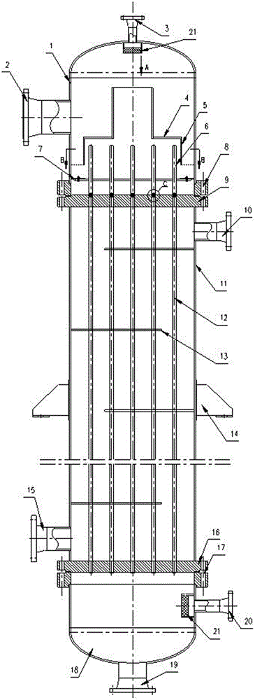
[0025] A vertical tube falling film evaporator, comprising an upper tube box 1, a lower tube box 18, a shell 11, a plurality of heat exchange tubes 12, an upper tube sheet 9 and a lower tube sheet 16, the upper end of the shell 11 and the upper tube box 1 Sealed connection, the lower end of the shell 11 is sealed with the lower tube box 18; the upper end of the shell 11 is provided with an upper tube plate 9, the lower end of the shell is provided with a lower tube plate 16, and the upper tube plate 9 and the lower tube plate 16 are A plurality of installation holes for installing the heat exchange tubes 12 are respectively provided, and the plurality of heat exchange tubes 12 are vertically installed in an array through the installation holes between the upper tube plate 9 and the lower tube plate 16, and the outer wall of the heat exchange tubes 12 is in contact with the ...


PUM


Abstract

The invention relates to a vertical tube type falling-film evaporator. The vertical tube type falling-film evaporator comprises an upper tube box, a lower tube box, a casing, multiple heat exchange tubes, an upper tube plate and a lower tube plate, wherein a solution inlet and a secondary steam outlet I are arranged at the upper tube box, a concentrated liquid outlet and a secondary steam outlet II are arranged at the lower tube box, a steam inlet is arranged at the upper part of the casing, and a condensed water outlet is arranged at the lower part of the casing; a film distributing device used for distributing a solution on the inner walls of the heat exchange tubes is arranged in the upper tube box; the film distributing device comprises a liquid bearing plate, a liquid feeding plate, a liquid distributing plate and liquid guiding tubes. By means of a steam stripping effect generated by secondary steam and liquid films, the heat transferring push force and the evaporation efficiency are increased. The liquid films can be uniformly distributed by the film distributing device, the film forming is stable, the wall drying phenomenon is avoided, the recovery rate of secondary steam produced in an evaporator is high, the recovery is convenient, and the heat transferring efficiency is improved.

Description

technical field [0001] The invention relates to the technical field of falling film evaporation, in particular to a vertical tube falling film evaporator. Background technique [0002] Existing evaporators are mainly used to achieve evaporation and concentration of feed liquid, which are very typical chemical unit operation equipment in the industry, and are widely used in industrial production such as chemical industry, light industry, food, pharmaceuticals, seawater desalination, and sewage treatment. The existing evaporators are generally based on horizontal tube falling film and vertical tube falling film. In the vertical tube falling film evaporator, feed liquid is generally added to the evaporation chamber, and the solution is distributed to each heat exchange device through the film distribution device. Inside the tube, it flows downward in the form of a film along the inner wall of the heat exchange tube. During the flow of the film-like material liquid, the material...

Claims


Application Information

Patent Timeline
Patent Type & Authority Applications(China)
IPC IPC(8): B01D1/06B01D1/22
CPCB01D1/065Y02A20/124
Inventor 武晓伟肖昌辉曾东常佳胡高林
Owner LUOYANG SUNRUI SPECIAL EQUIP
Why Eureka
Try Eureka