Shielding device with vacuum cavity body

A vacuum chamber and magnetic fluid technology, applied in vacuum evaporation plating, ion implantation plating, metal material coating process, etc., can solve the problems of high production cost and complex structure, and achieve high efficiency, simple structure, and economical efficiency. The effect of production costs

Inactive Publication Date: 2010-06-30
DONGGUAN ANWELL DIGITAL MASCH CO LTD
View PDF0 Cites 13 Cited by
  • Summary
  • Abstract
  • Description
  • Claims
  • Application Information

AI Technical Summary

Problems solved by technology

However, the existing control mechanisms all have the disadvantages of complex structure and high production cost. Therefore, there is an urgent

Method used


Image

  • Shielding device with vacuum cavity body
  • Shielding device with vacuum cavity body
  • Shielding device with vacuum cavity body

Examples


Example Embodiment

[0013] In order to describe in detail the technical content and structural features of the vacuum chamber shielding device of the present invention, further description will be given below with reference to the embodiments and the accompanying drawings.

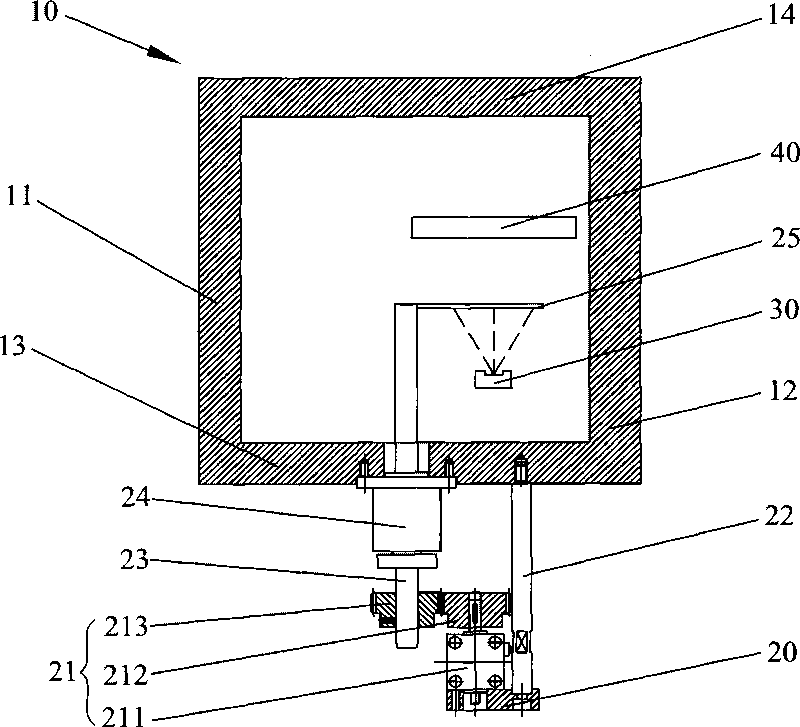
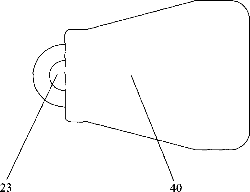
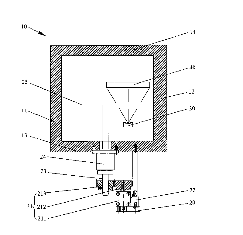
[0014] see figure 1 and figure 2 . exist figure 1 and figure 2 , the vacuum chamber 10 is surrounded by a left side wall 11 , a right side wall 12 , a bottom wall 13 and a top wall 14 to form a hollow sealing structure. The processing plate 40 is disposed in the vacuum chamber 10 and above the evaporation source 30 . The vacuum chamber shielding device of the present invention is suitable for shielding the evaporation source 30 and the processing plate 40 in the vacuum chamber 10 for providing vacuum coating, and includes a support base 20, a driving mechanism 21, a fixed rod 22, a rotating shaft 23, a magnetic Fluid 24 and baffle 25. The fixing rod 22 is fixed on one end of the support base 20 to strengthen the suppo...


PUM


Abstract

The invention provides a shielding device with a vacuum cavity body, comprising a support seat, a drive mechanism, a rotating shaft and a baffle. The drive mechanism comprises a motor, a drive gear and a driven gear, wherein the motor is fixed on the support seat; the output shaft of the motor is pivoted with the drive gear; the driven gear is engaged with the drive gear; one end of the rotating shaft is pivoted with the driven gear; the other end hermetically passes through the cavity wall of the vacuum cavity body and is vertically and fixedly connected with the baffle; the baffle is accommodated in the vacuum cavity body and positioned between an evaporation source in the vacuum cavity body and a processing board; and the drive mechanism drives the rotating shaft, and the rotating shaft drives the baffle to isolate or switch on a space of the evaporation source and the processing board. The shielding device with the vacuum cavity body has the advantages of simple structure, high evaporation efficiency and prolonged service life of the evaporation source.

Description

technical field [0001] The invention relates to a shielding device for organic light emitting diodes, in particular to a shielding device suitable for shielding evaporation sources in the vacuum coating process of organic light emitting diodes. Background technique [0002] OLED, namely Organic Light-Emitting Diode (Organic Light-Emitting Diode), also known as Organic Electroluminesence Display (OELD). Because of its thinness, power saving and other characteristics, it has been widely used in the display screen of digital products, and has a large market potential. At present, the application of OLED in the world is focused on flat panel displays, because OLED is the only application In terms of technology that can be compared with TFT-LCD, OLED is the only display technology that can produce large-size, high-brightness, high-resolution soft screens among all display technologies at present, and can be made into the same thickness as paper. Among them, in the OLED productio...

Claims


Application Information

Patent Timeline
IPC IPC(8): C23C14/04C23C14/24
Inventor 杨明生刘惠森范继良叶宗锋王曼媛王勇
Owner DONGGUAN ANWELL DIGITAL MASCH CO LTD
Why Eureka
Try Eureka