Centrifugal film evaporator

A thin film evaporator and evaporator technology, applied in evaporation, separation methods, chemical instruments and methods, etc., can solve the problems of long residence time, scraper power consumption, material changes, etc., to improve evaporation efficiency and effect, evaporation time The effect of shortening and saving energy

Inactive Publication Date: 2007-10-24
常熟市春来机械有限公司
View PDF0 Cites 15 Cited by
  • Summary
  • Abstract
  • Description
  • Claims
  • Application Information

AI Technical Summary

Problems solved by technology

[0003] However, although the existing thin-film evaporators such as vertically installed thin-film evaporators also belong to thin-film evaporation, the thin-film does not have a centrifugal effect, and only the gravity of the material forms a liquid film, so the liquid film is thicker and uniform. Poor, slow falling speed, long residence time (long heating time), which will lead to material changes; the scraper-type thin-film evaporator with a centrifugal scraper that acts on the liquid film is more efficient than the aforementioned evaporation that only relies on the gravity of the material superior
However, during the working process of the scraper, the scraper often rubs against the evaporator, that is, the evaporation film, and the impurities generated by the friction will enter the material, affecting the product quality, and the gap between the scraper and the evaporation film is difficult to maintain. In addition, the scraper needs to consume power, resulting in waste of energy such as electricity consumption

Method used


Image

  • Centrifugal film evaporator
  • Centrifugal film evaporator

Examples


Embodiment Construction

[0018] In order to enable the examiners of the patent office, especially the public, to further understand the structural features and beneficial effects of the present invention, the specific embodiments of the present invention are described in detail below with reference to the accompanying drawings and examples. However, the applicant declares that any change in form or modification in text based on the concept of the present invention shall be regarded as the scope of the technical solution disclosed in the present invention.

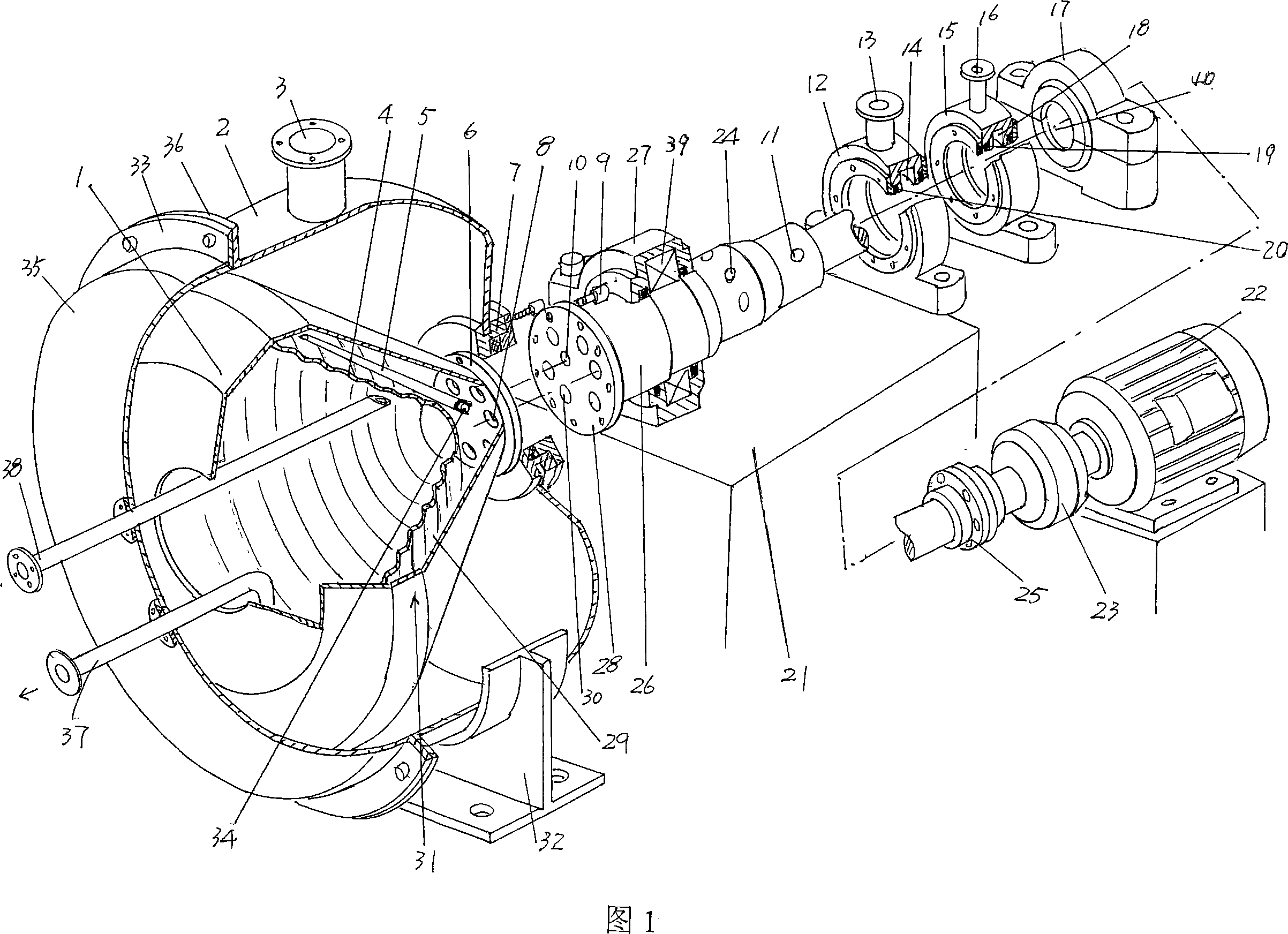
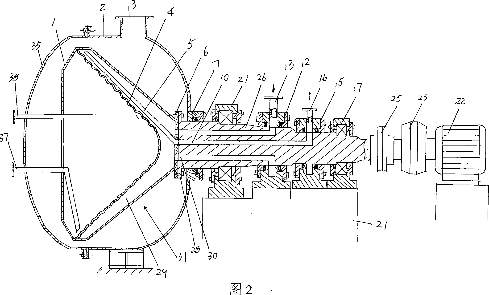
[0019] Please refer to FIG. 1 and FIG. 2. The motor 22 recommended by the present invention is a motor whose speed can be adjusted. When the centrifugal thin film evaporator of the present invention is installed and used, it should be horizontal. Therefore, the main shaft 26 It is connected with the power output shaft of the motor in a horizontal state, and is specifically connected through a coupling 25, and a hydraulic coupling 23 is also arranged...


PUM


Abstract

The invention relates to a centrifugal thin film evaporator for fluid even distribution in fluid film for evaporation and condensation, comprising a power and a main shaft connected to the power drive with evaporation channel and condensation return duct, evaporation introducer and condensation fluid extractor on the main shaft, a barrel with evaporator return opening equipped at the end of the main shaft, an isolation sleeve inside the barrel cavity and connected to the main shaft, an evaporator inside the isolation sleeve and fixed with the said isolation sleeve with evaporator cavity formed by the evaporator and the wall of the isolation sleeve and the evaporator cavity connecting to the evaporator channel and condensation duct respectively. It can shorten the evaporation period of material on the evaporator, with even fluid film, conducive to the improvement of evaporation efficiency and effect with energy conservation.

Description

technical field [0001] The invention relates to a centrifugal thin film evaporator, which is used for distributing liquid into a uniform liquid film for evaporation or concentration, and is applied to industries such as Chinese and Western pharmaceuticals, food, light industry, petrochemical industry, environmental protection and the like. Background technique [0002] The centrifugal thin film evaporator has a short evaporation time, and the evaporation process can be completed in only 1 second or even less than 1 second, so as to ensure that the extract remains in the original state and does not change. Due to the large number of materials, some materials, such as some natural pigments, are highly thermally sensitive. When the temperature is high and the time is long, the properties will change, which will affect the quality in the light, and cause the material to be scrapped in the worst. The boiling point temperature of the solvent is one of the reasons why people attach...

Claims


Application Information

Patent Timeline
Patent Type & Authority Applications(China)
IPC IPC(8): B01D1/22
Inventor 吕鸣冈王庆范建兵张诚陈志英
Owner 常熟市春来机械有限公司
Why Eureka
Try Eureka