Drop dispenser

a dispenser and drop technology, applied in the field of drop dispensers, can solve problems such as problematic drop remainders, and achieve the effect of constant drop sizes

Active Publication Date: 2014-07-08
APTAR RADOLFZELL
View PDF17 Cites 5 Cited by
  • Summary
  • Abstract
  • Description
  • Claims
  • Application Information

AI Technical Summary

Benefits of technology

[0010]The drop-formation area surrounding the discharge opening having a combination of a taper and a hydrophilic design has proven to be advantageous, particularly in respect of the evaporation time of the drop remainder. Compared to a planar design of a drop-formation area and under the assumption of an equal external diameter of the drop remainder remaining on the dispenser, this design provides a larger area over which the drop remainder is distributed. Moreover, it was observed that the drop remainder usually has a smaller volume.
[0012]In principle, this advantage of the reduced evaporation time is also provided if it is not only a delimited drop-formation area which has a hydrophilic design, but rather the whole dispenser on its outside. However, in order to create a defined drop size it is considered to be advantageous if the drop-formation area is spatially delimited. By way of example, this can be achieved by virtue of the drop-formation area being surrounded by a surrounding area which has a lower hydrophilicity than the drop-formation area. The hydrophilicity of the surrounding area surrounding the drop-formation area is preferably such that, under the aforementioned boundary conditions, it leads to a contact angle greater than 20°, preferably greater than 45°. The jump thus provided in respect of the hydrophilicity between the drop-formation area and the surrounding area causes the separation of the main drop from the drop remainder usually to take place without liquid reaching the region of the surrounding area in advance via the outer limit of the drop-formation area.
[0016]As a result of the tapering or conical shaping, the drop-formation area and the outer areas in the region of the discharge opening naturally add up to an overall area which is greater than the aforementioned values because the latter relate to the projection. It is precisely this actual drop-formation area which is enlarged compared to the projection area that ensures the reduced evaporation time.

Problems solved by technology

The aforementioned drop remainder was found to be problematic in the past.
This is problematic because this drop remainder can become a carrier of a contamination.

Method used


Image

  • Drop dispenser
  • Drop dispenser
  • Drop dispenser

Examples


Embodiment Construction

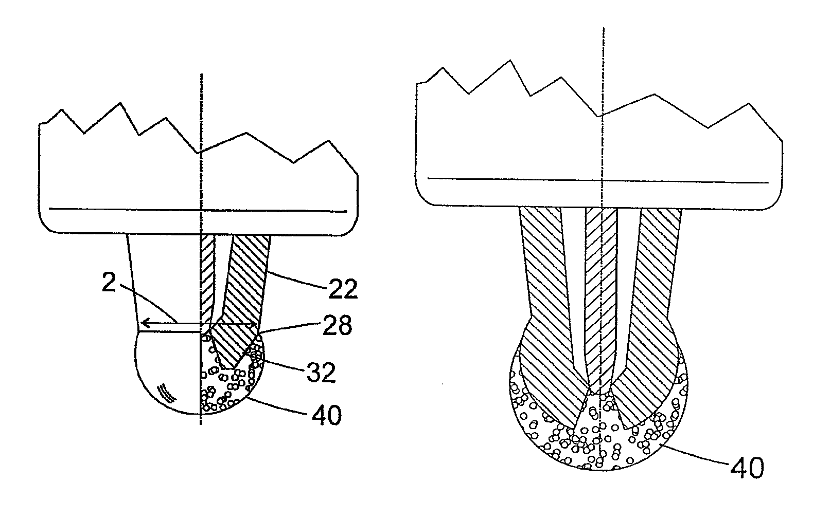
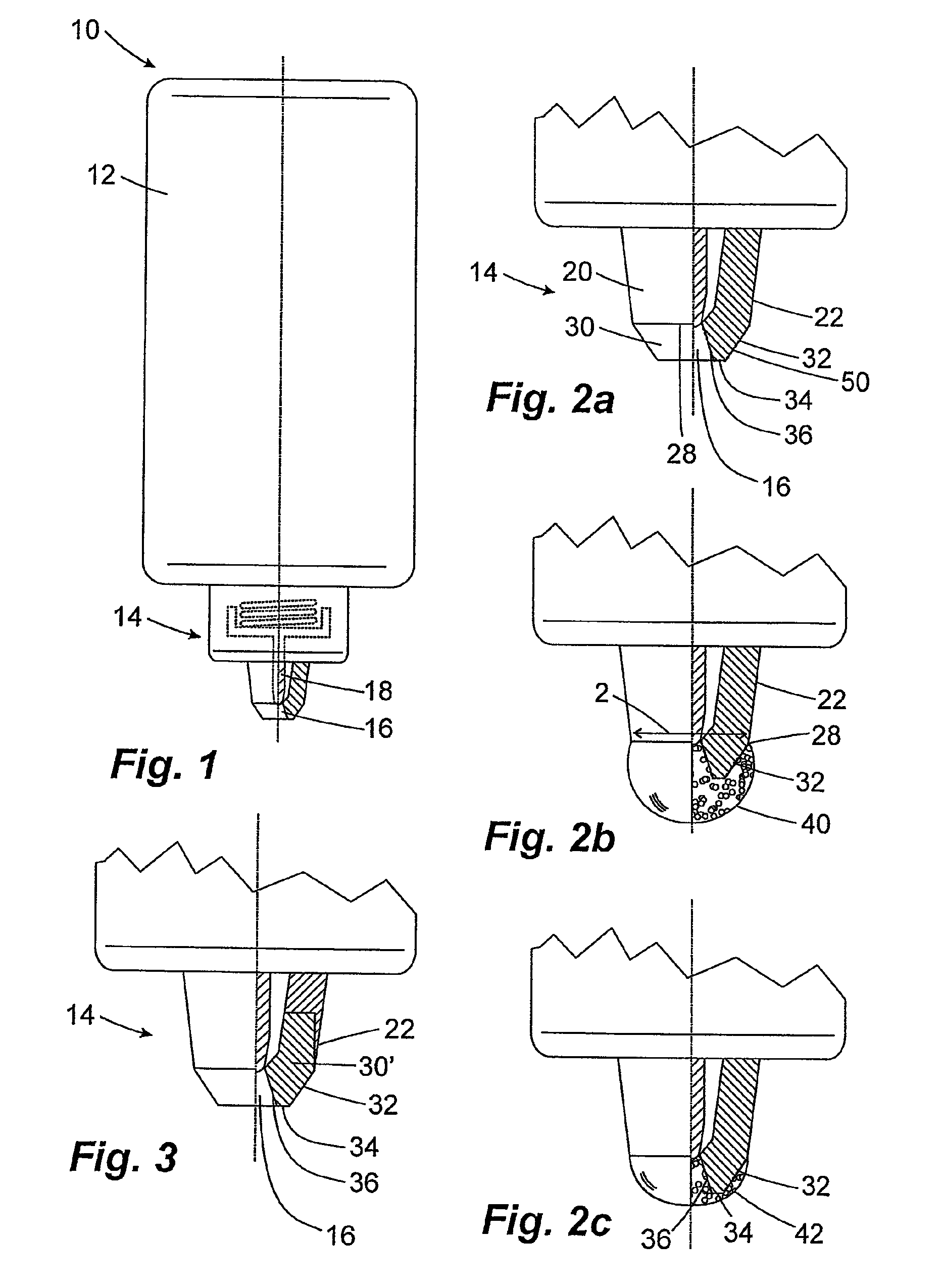
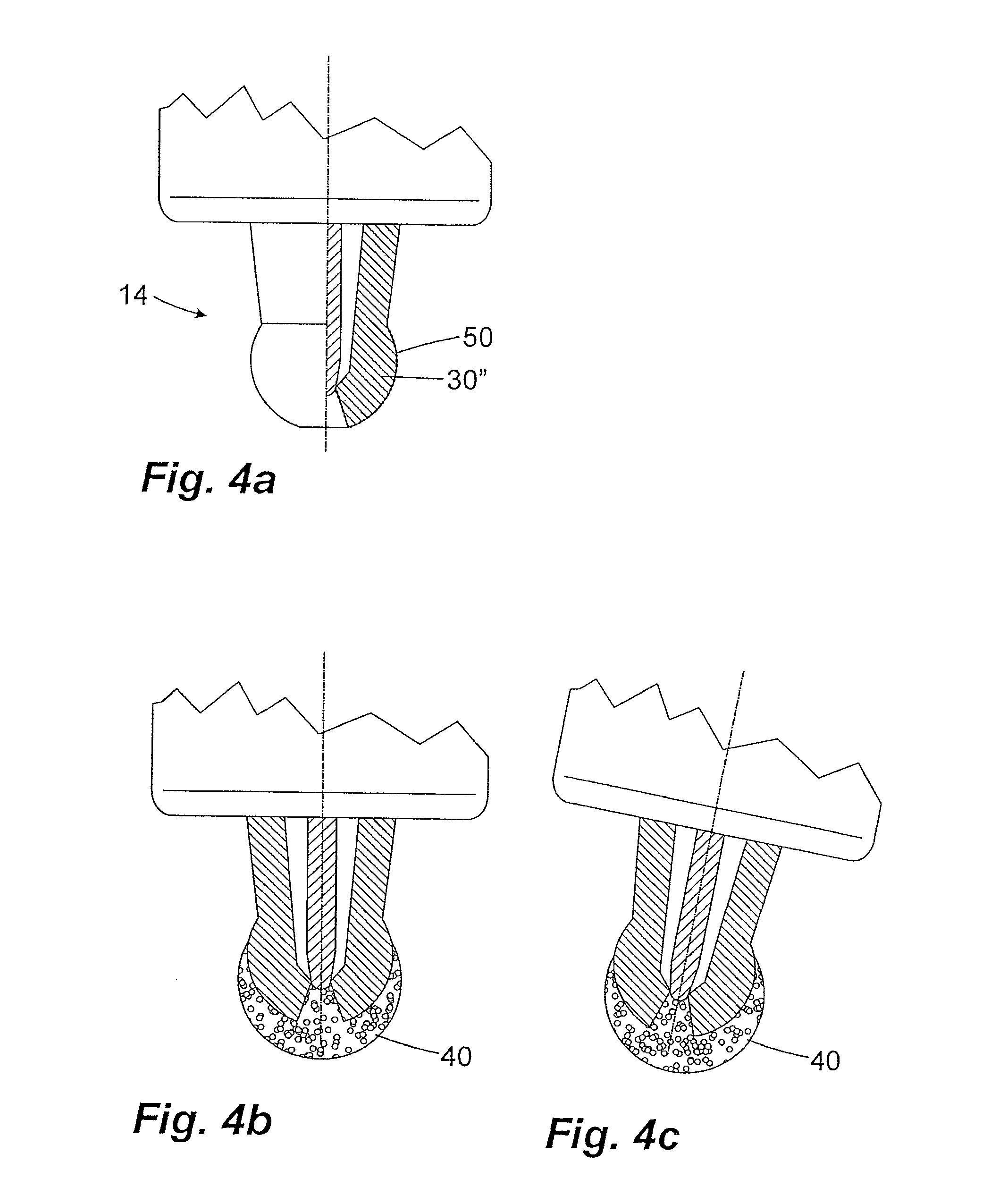
[0030]FIG. 1 shows an overall view of a drop dispenser according to the invention. The drop dispenser 10 has a liquid storage 12, which is embodied as a squeeze bottle. In a usage position, an outlet unit 14 of the drop dispenser 10 is directed downwards. This outlet unit comprises an outlet opening 16, which is closed by a valve pin 18 in the closed state of the dispenser 10. The valve pin 18 is part of a valve, indicated by dashed lines in FIG. 1, which opens and closes depending on the liquid pressure within the drop dispenser 10. In order to discharge liquid from the liquid storage 12 through the outlet opening 16, the liquid storage 12 is compressed by hand. This causes an increase in pressure and opens the valve by displacing the valve pin 18. If used as intended, the emerging liquid collects in the region of the outlet opening 16 and forms a drop there, the greater part of which separates from the dispenser after a specific size is reached while a smaller part, referred to as...


PUM


Abstract

Drop dispenser for releasing a pharmaceutical liquid in drop form, with a housing, a liquid storage and a discharge opening, which penetrates a wall of the housing and to which an outlet valve is assigned, for extracting the liquid. The discharge opening is surrounded by a drop-formation area on the outside of the housing, wherein this drop-formation area, at least in an outer region with respect to an alignment of the drop dispenser with the discharge opening pointing vertically downwards, has a shape tapering downwards and towards the discharge opening. The drop dispenser allows the release of drops with a constant size and shortens drying time.

Description

CROSS REFERENCE TO RELATED APPLICATION[0001]This application claims priority from German Application No. 10 2011 083 355.2, filed Sep. 23, 2011, the disclosure of which is hereby incorporated by reference in its entirety into this application.FIELD OF THE INVENTION[0002]The invention relates to a drop dispenser for releasing a pharmaceutical liquid in drop form. In this case, such a generic drop dispenser has a housing and a liquid storage, as well as a discharge opening, which penetrates a wall of the housing and to which an outlet valve is assigned, for extracting the liquid.BACKGROUND OF THE INVENTION[0003]Drop dispensers are generally known from the prior art for administering various medicaments. They have a liquid storage, which can for example be embodied as a squeeze bottle and brings about delivery of the liquid through the discharge opening as a result of compression and simultaneously having the discharge opening pointing downwards. If used as intended, a drop is formed o...

Claims


Application Information

Patent Timeline
Patent Type & Authority Patents(United States)
IPC IPC(8): B65D47/18B01L3/00B01L3/02
CPCB65D47/18A61F9/0008B01L3/00B01L3/0272B01L2300/161B65D47/2068
Inventor WOCHELE, MATTHIAS
Owner APTAR RADOLFZELL
Why Eureka
Try Eureka