
Two-dimensional pointing mechanism for space optical remote sensing instrument

A pointing mechanism and instrument technology, applied in the field of new high-precision two-dimensional pointing mechanism, to achieve the effect of ensuring assembly quality, simple structure, and ensuring operation accuracy

Inactive Publication Date: 2016-03-23
SHANGHAI INST OF TECHNICAL PHYSICS - CHINESE ACAD OF SCI
View PDF0 Cites 8 Cited by
  • Summary
  • Abstract
  • Description
  • Claims
  • Application Information

AI Technical Summary

Problems solved by technology

However, due to the use of two sets of mechanisms, the two scanning mirrors

Method used


Image

  • Two-dimensional pointing mechanism for space optical remote sensing instrument
  • Two-dimensional pointing mechanism for space optical remote sensing instrument
  • Two-dimensional pointing mechanism for space optical remote sensing instrument

Examples


Embodiment Construction

[0027] The following will be described in detail in conjunction with the accompanying drawings in order to better illustrate the structural features and functional features of the present invention, rather than limiting the protection scope of the present invention.

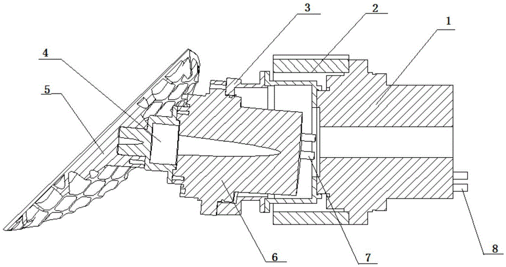
[0028] attached figure 1 The present invention is identified in detail—the configuration of a high-precision two-dimensional pointing mechanism. The mechanism mainly includes: pitch axis assembly, azimuth axis assembly, pitch and azimuth connection assembly and pointing mirror assembly, etc. The following is a detailed discussion. The composition of the pitch axis assembly and the azimuth axis assembly is the same, including: a drive motor, a feedback control detection element, and a reducer. The difference is: since the azimuth axis assembly is a load relative to the pitch axis system, the power of the pitch axis drive motor is greater than that of the azimuth axis drive motor.

[0029] The selection of the dr...


PUM


Abstract

The invention discloses a two-dimensional pointing mechanism for a space optical remote sensing instrument. The two-dimensional pointing mechanism is composed of an installation machine seat, an azimuth axis drive assembly, a pitch axis drive assembly and a pointing mirror assembly, wherein the azimuth axis drive assembly comprises a drive servo motor, a high-accuracy encoder and a harmonic reducer, and the pitch axis drive assembly comprises a servo drive motor, a high-accuracy encoder, a harmonic reducer and an azimuth axis connecting piece. The two-dimensional pointing mechanism has the beneficial effects that compared with a traditional two-dimensional pointing mechanism, the two-dimensional pointing mechanism is high in pointing accuracy, simple in structure, small in load, low in assembling difficulty and the like; and meanwhile, the mechanism can continuously rotate by 360 degrees in one dimension, and the functions of in-orbit calibration and the like of the space optical remote sensing instrument can be achieved.

Description

technical field [0001] The invention relates to a novel high-precision two-dimensional pointing mechanism for space optical remote sensing instruments. The mechanism is mainly used in the optical pointing of area array optical remote sensing instruments to increase the observation range of area array optical remote sensing instruments. At the same time, since one dimension of the mechanism can continuously scan 360°, it can realize spectral calibration of optical remote sensing instruments, which is beneficial to the on-orbit quantitative application of remote sensing instruments. Background technique [0002] In recent years, with the development of electronic science and technology, large-scale detector arrays have been more and more widely used in optical remote sensing instruments. The performance of remote sensing instruments has been greatly improved, and ground resolution and spectral resolution have been improved. A substantial increase. At the same time, with the b...

Claims


Application Information

Patent Timeline
IPC IPC(8): B25J9/16
CPCB25J9/1605
Inventor 刘晓华李峰郑庚
Owner SHANGHAI INST OF TECHNICAL PHYSICS - CHINESE ACAD OF SCI
Learn More