Designing method for valve port of rotary valve

A design method and technology of rotary valve, applied in the direction of calculation, earthwork drilling, special data processing applications, etc., can solve the problem that it does not have the characteristics of wave propagation, cannot provide effective solutions and solutions, and does not explain the theoretical basis for valve port design. and design methods

Inactive Publication Date: 2016-03-23
CHINA UNIV OF PETROLEUM (EAST CHINA) +1
View PDF9 Cites 7 Cited by
  • Summary
  • Abstract
  • Description
  • Claims
  • Application Information

AI Technical Summary

Problems solved by technology

The structural design of the valve port of the rotary valve is based on the mathematical model of the drilling fluid pressure wave. Both pointed out that the pressure mutation caused by the water hammer (water hammer) effect of fluid unsteady flow, this pressure change has the characteristics of wave propagation; but the water hammer pressure expression can only reflect the pressure mutation phenomenon caused by the sudden closure of the valve port, and cannot Reflects the influence of fluid motion control body parameters such as valve closing speed and valve port structure on unsteady flow pressure, so water hammer pressure is not suitable for the mathematical description of drilling fluid pressure signals
Regarding the valve port design of rotary valves, U.S. Patents U.S. Pat. No. 5237540, 5586083, 5636178, 5787052, 6970398, 7327634, 7468679, literature SPE67762, etc. have given a variety of valve port structures, but none of them have explained the theory of valve port design Based on and design method, U.S. Patent U.S.Pat.No.4847815 introduces a valve port structure, briefly describes the influence of valve hole flow area, drilling fluid flow rate and density on the pressure signal amplitude and waveform, and uses this as the valve port structure According to the design basis, the waveform distortion of the pressure signal generated by the rotary valve with the valve port structure at constant speed is 21%, but the mathematical model of the pressure signal described in this document is the pressure loss generated at the valve hole when the fluid flows stably. Since the pressure loss does not have the characteristics of wave propagation, there are great doubts about the structure of the rotary valve port given by it.
Therefore, how to correctly establish the mathematical model of the drilling fluid pressure signal according to the generation mechanism of the drilling fluid pressure wave, and how to realize the structural design of the rotary valve port based on the mathematical model of the drilling fluid pressure signal, none of the existing technologies can provide an effective solution. and solution

Method used


Image

  • Designing method for valve port of rotary valve
  • Designing method for valve port of rotary valve
  • Designing method for valve port of rotary valve

Examples


Embodiment Construction

[0045] The present invention will be further described below in conjunction with the accompanying drawings and embodiments.

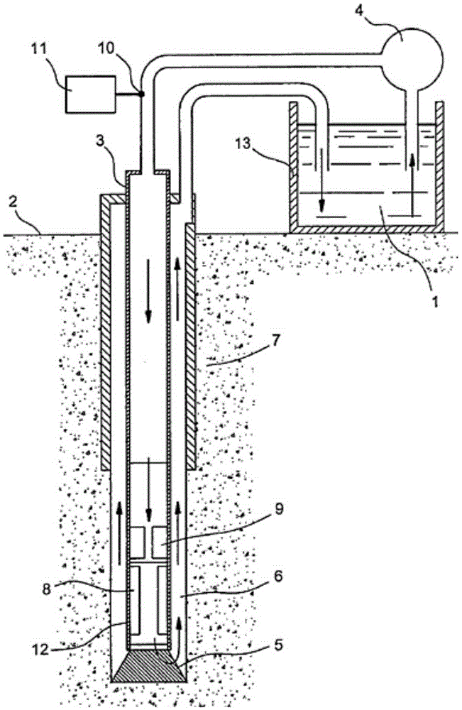
[0046] figure 1 Shown is an existing drilling device including a measurement-while-drilling / logging-while-drilling tool and a drilling fluid continuous pressure wave signal generator. The drilling fluid 1 in the drilling fluid tank 13 is injected into the drill string 3 drilled into the formation 7 through the drilling fluid pump 4 on the ground 2, reaches the drill bit 5 at the bottom of the drill string 3, and passes through the drill string 3 and the formation 7 after flowing out from the water hole of the drill bit. The annular space 6 between returns to the surface 2, and the arrow indicates the flow path of the drilling fluid.

[0047] Instruments are placed in the drill collar 12 close to the drill bit 5 in the drill string 3 , and the upper part of the drill collar is connected to the drill pipe to form a drill string. The entire drill string a...


PUM


Abstract

The invention provides a designing method for a valve port of a rotary valve, which is used for developing a rotary valve type drilling fluid pressure signal generator for measuring while drilling/well logging while drilling. The designing method comprises the steps of establishing a mathematical model of a drilling fluid pressure signal according to the inertial pressure analysis of unstable flow of a fluid; establishing a mathematical model of a continuous drilling fluid pressure wave signal generated at the valve port of the rotary valve at a constant rotating speed on the basis of the mathematical model; and obtaining planar structures of a stator port and a rotor port of the rotary valve through mathematical analysis and numerical calculation to realize the structural design of the valve port of the rotary valve. Due to the adoption of the valve port structure of the rotary valve designed by using the method, the waveform of the drilling fluid pressure signal generated at the valve port of the rotary valve at the constant rotating speed more approaches to a sine wave and has a wave propagation characteristic; and the distortion degree of the waveform of the pressure signal is relatively low, and the energy of the signal is more gathered at a fundamental wave, which is beneficial to the modulation of measuring while drilling/well logging while drilling data and the transmission of the modulated continuous drilling fluid pressure wave signal.

Description

Technical field: [0001] The invention relates to a design method of a measurement-while-drilling / logging-while-drilling tool in the oil and gas drilling process, in particular to a design method of a rotary valve port used in a drilling fluid pressure signal generator. Background technique: [0002] Downhole Measurement While Drilling / Logging While Drilling (MWD / LWD) is a modern drilling auxiliary technology that measures and transmits downhole information in real time during drilling. During the drilling process, the drilling fluid is pumped downhole from the surface through the drill string, sprayed out from the water hole of the drill bit for the lubrication and cooling of the drill bit, and returns upward to the wellhead through the annular space between the well wall and the drill string. MWD / LWD tools are installed Inside the drill collar at the top of the bit, see attached figure 1 . In MWD / LWD tools, sensors installed in the drill string near the drill bit obtain m...

Claims


Application Information

Patent Timeline
Patent Type & Authority Applications(China)
IPC IPC(8): E21B21/10E21B47/20G06F19/00
CPCG16Z99/00E21B21/10E21B47/20
Inventor 沈跃盛利民
Owner CHINA UNIV OF PETROLEUM (EAST CHINA)
Why Eureka
Try Eureka