An Improved Triangular Piston Rotary Compression-Expander

A rotary compression and improved technology, applied in the field of improved triangular piston rotary compression expanders, can solve problems such as poor sealing performance, consumption of lubricating oil, cylinder piston wear, etc., to reduce difficulty and cost, reduce friction loss, improve The effect of sealing performance

Inactive Publication Date: 2018-03-20
滕士贤
View PDF6 Cites 0 Cited by
  • Summary
  • Abstract
  • Description
  • Claims
  • Application Information

AI Technical Summary

Problems solved by technology

Because the cylinder piston is a sliding contact with semi-dry lubricating oil, rather than a rolling contact with little resistance and wear, it is not only laborious but also inevitably has many defects such as so-called "vibration marks" and poor sealing performance, and its service life will inevitably be greatly improved. However, due to the high operating temperature of the cylinder piston and the aerobic combustion, it will burn and consume a large amount of lubricating oil, so only semi-dry sliding contact lubrication can be used, and its sealing performance is poor, and the compression ratio and working The efficiency will be greatly reduced, and its service life will inevitably be greatly shortened.
[0005] One of the inventors of the present invention applied for a triangular piston rotary compression-expander (application number is 200920054727.2) on April 15, 2009. Low, due to the frictional contact between the inner rotor and the outer rotor, the cylinder piston is severely worn and easily damaged. It requires high machining accuracy and smoothness and good materials to meet the requirements. The friction loss is large and the sealing performance is poor, which increases the processing difficulty. , the processing cost is high, but the effect is not ideal. However, the reason why the existing triangular piston rotary engine cannot be widely used is mainly due to its serious defects such as "vibration lines" that are difficult to solve and poor sealing performance.

Method used


Image

  • An Improved Triangular Piston Rotary Compression-Expander
  • An Improved Triangular Piston Rotary Compression-Expander
  • An Improved Triangular Piston Rotary Compression-Expander

Examples


Embodiment 1

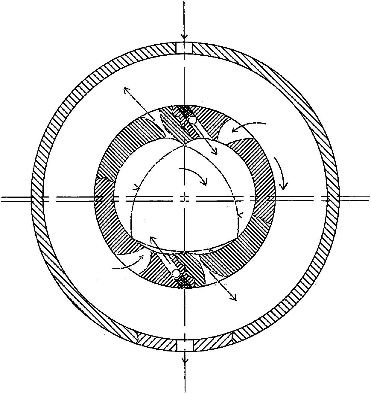
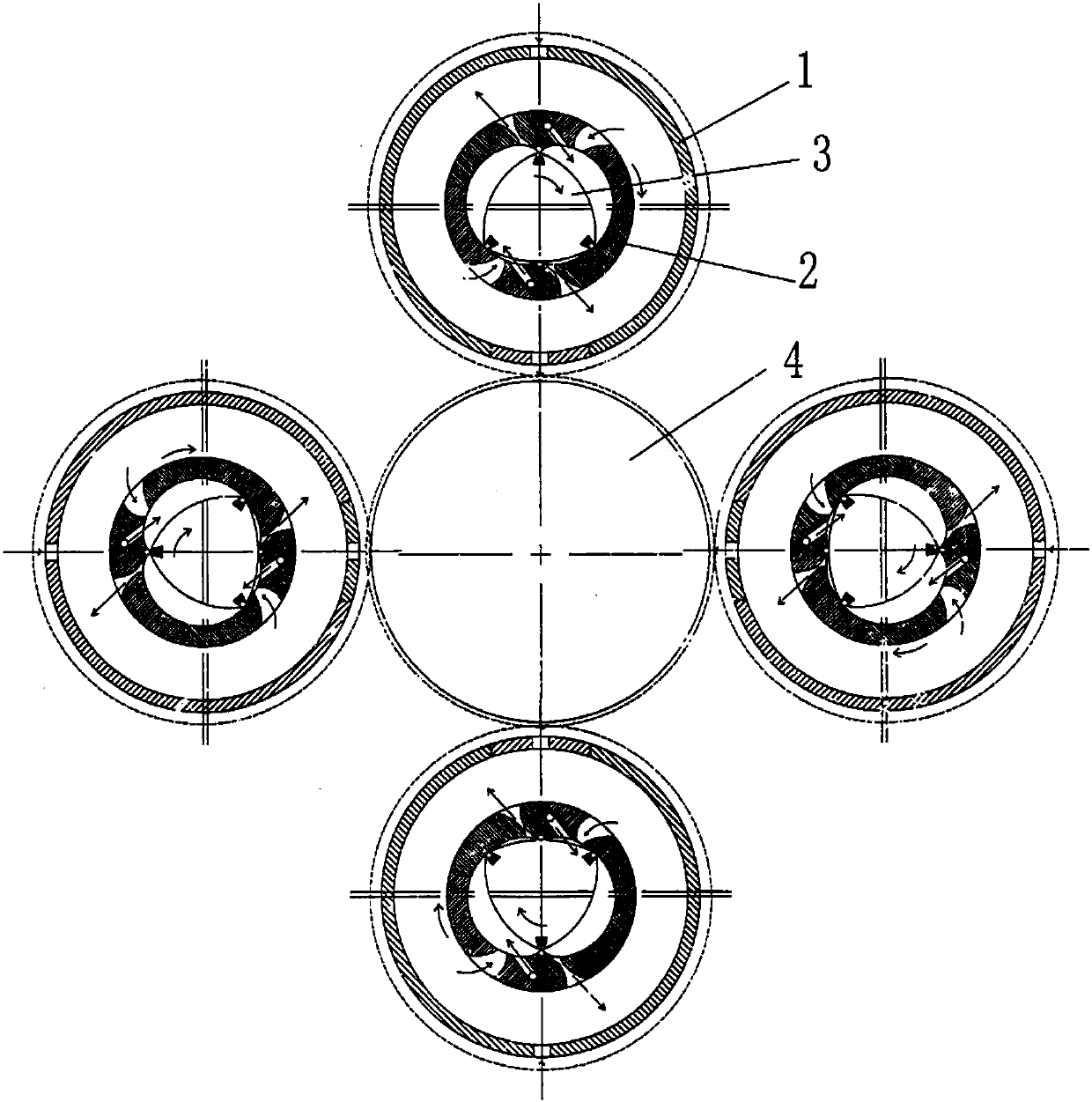
[0033] An improved triangular piston rotary compression expander, including power gears and four single-cylinder units, such as figure 2 , image 3 As shown, the four single-cylinder units are evenly arranged outside the power gear. The single-cylinder unit includes a sleeve, an outer rotor and an inner rotor located in the sleeve. There is a cavity inside the outer rotor, and two centrally symmetrical The inner wall of the cavity between the two convex ribs is a concave inner wall, the inner rotor is located in the cavity, the outer wall of the inner rotor is provided with three raised edges, and the arc side is between two adjacent edges. In order to reduce the defects of sliding contact between the inner rotor and the outer rotor in the prior art, dovetail grooves are arranged on the edges, and elastic rolling components are arranged in the dovetail grooves. The notch width of the dovetail groove is smaller than the width of the bottom of the groove. The elastic rolling a...

Embodiment 2

[0041] An improved triangular piston rotary compression expander, its structure is as described in Embodiment 1, the difference is that two ribs of the outer rotor are provided with dovetail grooves along the ribs, and elastic rolling components are arranged in the dovetail grooves. There are also elastic rolling assemblies on the two ribs on the inner wall of the outer rotor cavity, so that the ribs form rolling contact with the edges and the arc-shaped side wall of the inner rotor, and the edges form elastic rolling contact with the ribs and the concave inner wall of the outer rotor. , to further enhance the effect of rolling contact.

Embodiment 3

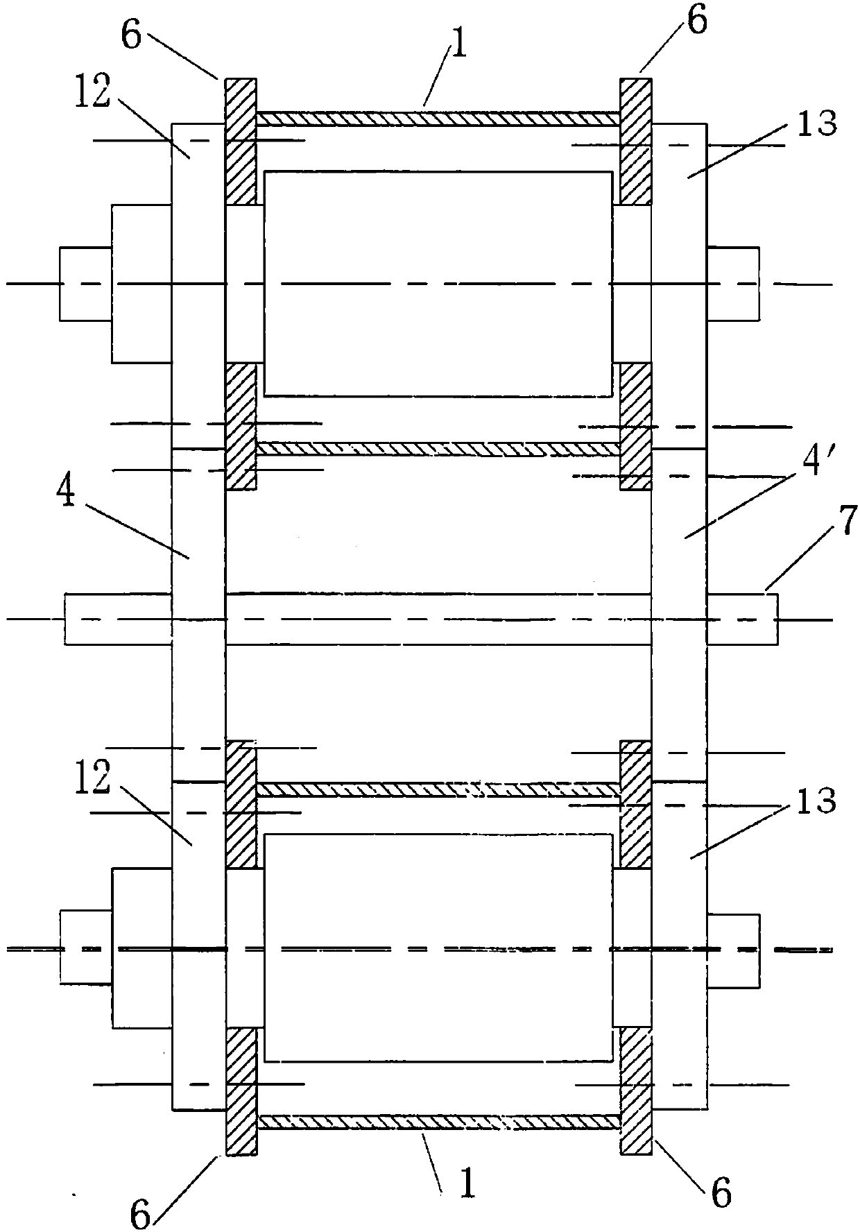
[0043] An improved triangular piston rotary compression expander, the structure of which is as described in Embodiment 1, the difference is that elastic sealing rings are provided between the inner rotor, the outer rotor and the two ends of the elastic rolling assembly and the outer rotor shaft, which can Apply high-pressure engine oil to the outer sides of the elastic sealing rings at both ends, and the flow direction of the high-pressure engine oil is as follows: Figure 6 indicated by the middle arrow. The sealing performance of the whole machine is enhanced by applying high-pressure oil to the outside of the elastic sealing rings at both ends.


PUM


Abstract

The invention relates to an improved triangular piston rotary compression expander, which belongs to the technical field of power machinery and includes a power gear and at least one single-cylinder unit. The single-cylinder unit includes a sleeve and an outer rotor and an inner rotor located in the sleeve. There is a cavity inside, and the inner wall of the cavity is provided with two symmetrical convex ribs, the inner wall of the cavity between the two convex ribs is a concave inner wall, the inner rotor is located in the cavity, and the outer wall of the inner rotor is provided with three raised ribs. Edges, arc-shaped side walls between two adjacent edges, dovetail grooves are provided on the edges and convex ribs, elastic rolling components are arranged in the dovetail grooves, and elastic rolling components are used to make the edges, side walls and space The inner wall of the cavity and the two convex ribs on the inner wall of the cavity form a rolling contact with little resistance and wear, which reduces friction loss, prolongs the service life of the whole machine, and makes up for the problems caused by materials, errors, and smoothness during processing, assembly, and operation. The negative impact of the sealing effect is good, the processing difficulty and cost are reduced, and the conversion efficiency of the whole machine is improved.

Description

technical field [0001] The invention relates to an improved triangular piston rotary compression expander, which belongs to the technical field of power machinery that utilizes renewable new energy, is environmentally friendly, carbon-free and pollutant-free. Background technique [0002] The expander is a machine that uses the principle of outputting mechanical work when the compressed gas expands and depressurizes to reduce the temperature of the gas and even liquefy it to obtain energy. It is often used in cryogenic equipment. [0003] The Chinese patent document "Unit Combined Slider Piston Inner Rotor Engine" (application number 87102947.2) discloses that the unit combined slider piston inner rotor engine is a new design scheme for internal combustion engines. The cylinder (A1) line is drawn by two different radii Different circular arcs are tangentially connected to form an arc triangle; the profile line of the slider (A5) is an approximate ellipse created by the same ...

Claims


Application Information

Patent Timeline
Patent Type & Authority Patents(China)
IPC IPC(8): F01C1/30F01C21/08F01C21/10F01C11/00F01C17/02
CPCF01C1/30F01C11/002F01C17/02F01C21/08F01C21/10
Inventor 钟琼香滕士贤
Owner 滕士贤
Why Eureka
Try Eureka