Vaporized Fuel Processing Apparatus

一种蒸发燃料、处理装置的技术,应用在蒸发燃料处理装置领域,能够解决吸附材料温度下降等问题,达到提高脱离效率的效果

Inactive Publication Date: 2016-03-23
AISAN IND CO LTD
View PDF8 Cites 4 Cited by
  • Summary
  • Abstract
  • Description
  • Claims
  • Application Information

AI Technical Summary

Problems solved by technology

However, when the evaporated fuel is removed, the temperature of the adsorbent tends to drop due to the heat of vaporization of the evaporated fuel.

Method used


Image

  • Vaporized Fuel Processing Apparatus
  • Vaporized Fuel Processing Apparatus
  • Vaporized Fuel Processing Apparatus

Examples


Embodiment Construction

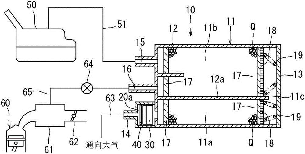
[0034] Hereinafter, representative embodiments of the present invention will be described. Such as figure 1As shown, the canister 10 includes a housing 11 . The housing 11 is made of resin, and is composed of a square cylindrical housing main body 12 and a lid 13 that closes the opening end surface of the housing main body 12 . The inside of the casing 11 (casing main body 12 ) is partitioned by the partition wall 12 a into two chambers, the first adsorption chamber 11 a and the second adsorption chamber 11 b. The two chambers 11 a and 11 b communicate with each other through a communication passage 11 c formed between the case main body 12 and the cover body 13 . Thereby, a U-shaped gas flow path is formed that communicates the first adsorption chamber 11a and the second adsorption chamber 11b through the communication passage 11c. In addition, in this embodiment, for the convenience of description, in figure 1 Although the canister 10 is illustrated in the horizontal d...


PUM


Abstract

A vaporized fuel processing apparatus has a casing defining an adsorption chamber therein and having a tank port, a purge port, and an atmospheric port. The tank port is connected to a fuel tank. The purge port is connected to an internal combustion engine. The atmospheric port is open to the atmosphere. A heater is disposed between the adsorption chamber and the atmospheric port and has a fin heat exchanger and a heating element. The heating element is configured to generate heat by electricity supply. The fin heat exchanger is joined to the heating element. The surface area of the fin heat exchanger between the heating element and the adsorption chamber is larger than the surface area of the fin heat exchanger between the heating element and the atmospheric port.

Description

technical field [0001] The present invention relates to an evaporated fuel processing device, which includes: an adsorption chamber containing an adsorption material capable of adsorbing and detaching evaporated fuel generated in a fuel tank, a tank port communicating with the fuel tank, and The vaporized fuel detached from the adsorption material is discharged to the purge port outside the adsorption chamber, the atmospheric port is opened to the atmosphere, and the heating device is arranged between the adsorption chamber and the atmospheric port. Background technique [0002] In order to prevent the evaporated fuel generated by the evaporation of the fuel stored in the fuel tank from being discharged outside the vehicle, vehicles such as automobiles are generally equipped with such evaporated fuel processing devices called adsorption canisters (hereinafter sometimes referred to as adsorption canisters). . Specifically, evaporated fuel generated in the fuel tank passes th...

Claims


Application Information

Patent Timeline
Patent Type & Authority Applications(China)
IPC IPC(8): F02M25/08
CPCF02M25/089F02D41/003F02M25/08F02M25/0854F02M2025/0881
Inventor 牧野胜彦木本顺也
Owner AISAN IND CO LTD
Why Eureka
Try Eureka