A New Type of Magnetic Control Butterfly Valve

A butterfly valve, a new type of technology, applied in the direction of lifting valves, valve details, valve devices, etc., can solve the problems of reducing the service life of butterfly valves, losses in the pipeline transportation industry, and large rotational torque of butterfly plates, so as to reduce the opening and closing torque and improve work. performance, the effect of solving leakage problems

Active Publication Date: 2018-06-22
ZHEJIANG SCI-TECH UNIV
View PDF5 Cites 0 Cited by
  • Summary
  • Abstract
  • Description
  • Claims
  • Application Information

AI Technical Summary

Problems solved by technology

Ordinary butterfly valves are connected to the valve core through the valve stem through the butterfly plate, which is easy to cause fatigue damage, and the rotational torque of the butterfly plate is relatively large. For ordinary butterfly valves, it is difficult to open the valve quickly.
When the fluid flows through the ordinary butterfly valve, it is easy to cause cavitation, which reduces the service life of the butterfly valve and causes huge losses to the pipeline transportation industry.

Method used


Image

  • A New Type of Magnetic Control Butterfly Valve
  • A New Type of Magnetic Control Butterfly Valve
  • A New Type of Magnetic Control Butterfly Valve

Examples


Embodiment Construction

[0027] The present invention will be further described below in conjunction with drawings and embodiments.

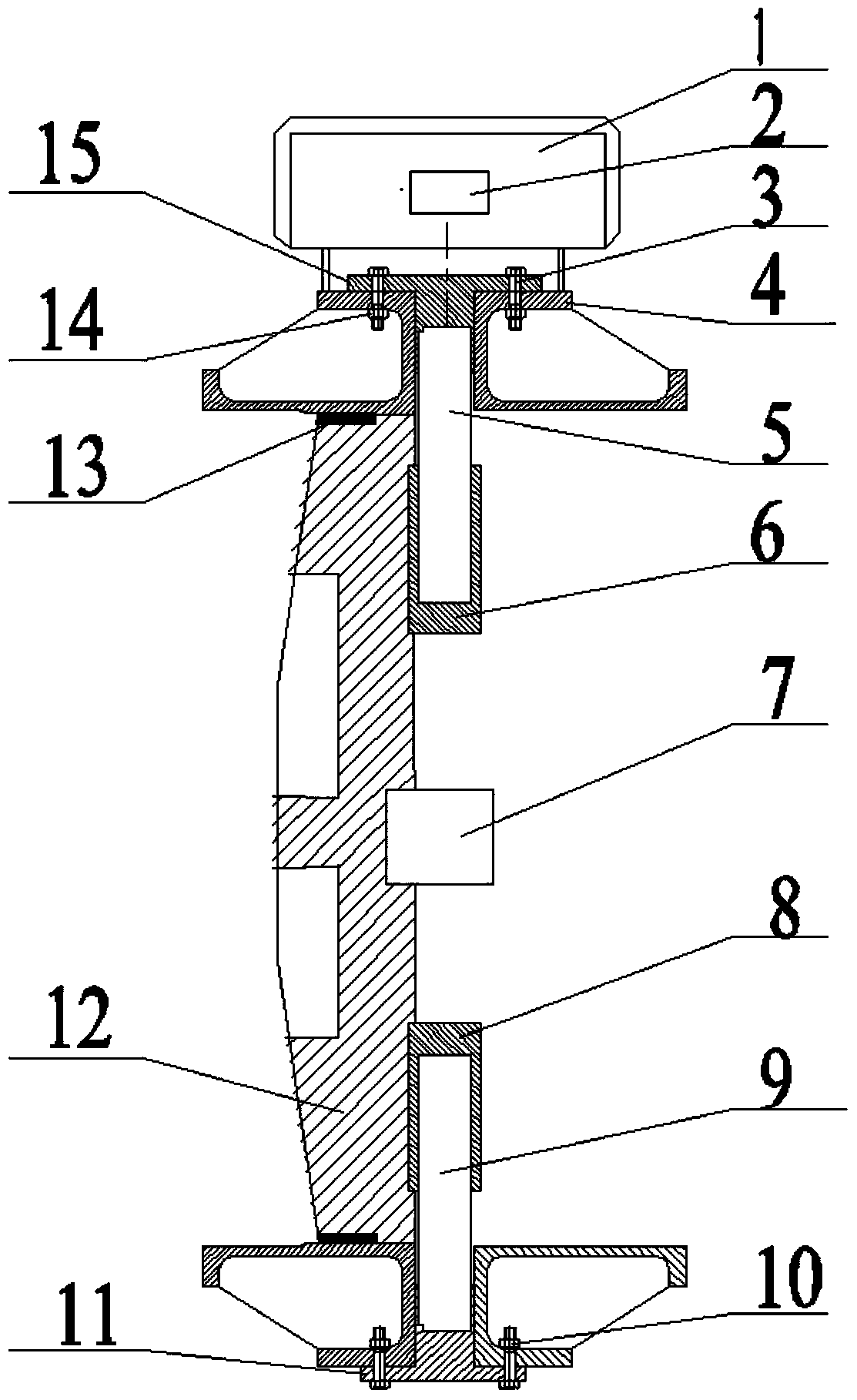
[0028] Such as figure 1 As shown, an electromagnetic controller 1 is installed on the valve body 4 of the present invention, and the electromagnetic controller 1 has an electromagnet 2 built in, and a butterfly plate 12 with a permanent magnet 7 is installed in the inner cavity of the valve body 4, and the butterfly plate 12 is driven by magnetic control. rotation;

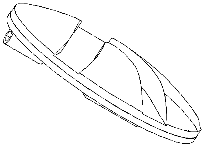
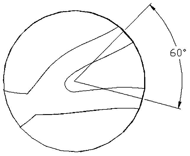
[0029] Upper bonnet 14 and lower bonnet 11 are respectively fixed on the upper and lower ends of valve body 4 by bolt 3, as Figure 5-6 As shown, the permanent magnet 7 is fixed in the middle of one end face of the butterfly plate 12, and the upper and lower parts of the end face of the butterfly plate 12 where the permanent magnet 7 is located are respectively fixed with a coaxial upper bushing 6 and a lower bushing 8, so that the butterfly plate 12 and the upper The valve stem 5 and the lower valve stem...


PUM


Abstract

The invention discloses a novel magnetic control butterfly valve. An electromagnetic controller is mounted on a valve body; an electromagnet is arranged inside the electromagnetic controller; a butterfly plate provided with a permanent magnet is mounted in an inner chamber of the valve body; an upper valve cover and a lower valve cover are fixed at the upper and lower ends of the valve body by boltsrespectively; the permanent magnet is fixed at the middle part of one end face of the butterfly plate; an upper shaft sleeve and a lower shaft sleeve which are coaxial to each other are fixed at the upper and lower parts of the end face, where the permanent magnet is positioned, of the butterfly platerespectively; the upper shaft sleeve and the lower shaft sleeve are matched and connected with the upper valve cover and the lower valve coverrespectively by an upper valve rod and a lower valve rod so that the butterfly plate can be mounted between the upper valve cover and the lower valve cover inside the valve body to form limited rotation; the other end face of the butterfly plate is provided with one inlet flow path and two outlet flow paths. The novel magnetic control butterfly valve disclosed by the invention is driven to rotate by rotation of the electromagnet inside the electromagnetic controller, so that the butterfly valve is controlled tobe opened and closed; the control theory of the butterfly valve is changed; flow division and decompression are carried out to reduce cavitation corrosion; vibration is prevented; noise is reduced; leakage problems of the butterfly valve are reduced; the working performance of the butterfly valve is improved; the butterfly valve is applicable to various occasions.

Description

technical field [0001] The invention relates to a butterfly valve, in particular to a novel magnetically controlled butterfly valve, which can complete the opening and closing work of the butterfly valve through the action of a magnetic field by utilizing the magnetism of a magnet. Background technique [0002] Butterfly valve, also known as flap valve, is a regulating valve with simple structure, which can be used for switch control of low-pressure pipeline medium, and can also be used to control air, water, steam, various corrosive media, mud, oil, liquid metal and radioactive The flow of various types of fluids such as media. It mainly plays the role of cutting and throttling on the pipeline. The opening and closing part of the butterfly valve is a disc-shaped butterfly plate that rotates around its own axis in the valve body to achieve the purpose of opening and closing or adjustment. [0003] With the acceleration of my country's urbanization process, the amount of va...

Claims


Application Information

Patent Timeline
Patent Type & Authority Patents(China)
IPC IPC(8): F16K1/22F16K1/36F16K47/04F16K47/02F16K31/08
CPCF16K1/221F16K1/222F16K31/0662F16K31/082F16K47/045
Inventor 林哲马传京许本亮朱祖超
Owner ZHEJIANG SCI-TECH UNIV
Why Eureka
Try Eureka