A fuel tank isolation valve
A technology of isolating valve and fuel tank, applied in the direction of lift valve, valve details, valve device, etc., can solve the problems of increasing system complexity, poor consistency of spring machining, and difficult control of spring cumulative error.
- Summary
- Abstract
- Description
- Claims
- Application Information
AI Technical Summary
Problems solved by technology
Method used
Image
Examples
Embodiment Construction
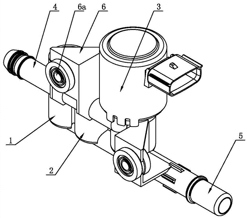
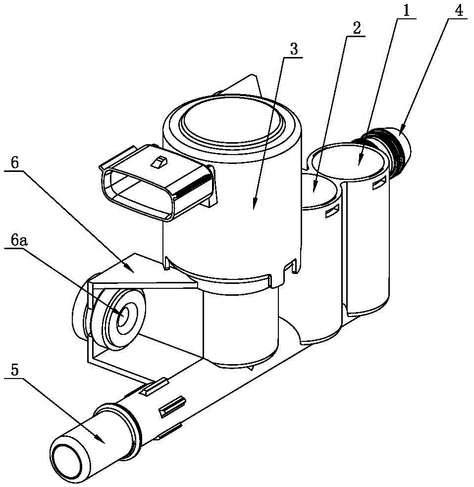
[0035] like Figure 1-7 A fuel tank isolation valve shown includes a fuel tank pipeline 5, a solenoid valve assembly 3, an air release valve assembly 1, an air supply valve assembly 2, and a carbon canister pipe 4, a valve body 301 of the solenoid valve assembly 3, and a second valve body of the air release valve assembly 1. The first housing 101 and the second housing 201 of the air supply valve assembly 2 are integrally formed, and the bottoms of the solenoid valve assembly 3, the air release valve assembly 1, and the air supply valve assembly 2 are all connected to the fuel tank pipeline 5 to form an air circuit The upper parts of the solenoid valve assembly 3, the air release valve assembly 1, and the air supply valve assembly 2 are all connected to the carbon canister pipeline 4, and form a gas path communication. The spaces are connected together through the shells between them;
[0036] The solenoid valve assembly 3 includes a support 306 that divides the valve body 30...
PUM
 Abstract
Description
Claims
Application Information
 - R&D
- Intellectual Property
- Life Sciences
- Materials
- Tech Scout
- Unparalleled Data Quality
- Higher Quality Content
- 60% Fewer Hallucinations
Browse by: Latest US Patents, China's latest patents, Technical Efficacy Thesaurus, Application Domain, Technology Topic, Popular Technical Reports.
© 2025 PatSnap. All rights reserved.Legal|Privacy policy|Modern Slavery Act Transparency Statement|Sitemap|About US| Contact US: help@patsnap.com


