Heat exchanger of oil tank heated by heat pump

A heat exchanger and hot oil tank technology, applied in the field of oil tanks, can solve the problems of small heating area, environmental pollution, and low comprehensive energy efficiency ratio, and achieve the effects of increasing cycle frequency, reducing cycle workload, and reducing cycle resistance

Inactive Publication Date: 2016-03-23
XIAMEN HAOBENG ELECTROMECHANICAL EQUIP CO LTD
View PDF9 Cites 2 Cited by
  • Summary
  • Abstract
  • Description
  • Claims
  • Application Information

AI Technical Summary

Problems solved by technology

[0002] The oil storage tank heating device disclosed in the prior art uses steam tube heating to heat the oil in the tank. However, the steam tube heater with this structure is a single round tube, so the heating area is very small. In addition, the heat source comes from the traditional oil-fired boiler, obviously its overall energy efficiency is relatively low, and at the same time, the boiler will cause corresponding pollution to the environment when it is burned, which is also a technical problem existing in the existing technical conditions

Method used


Image

  • Heat exchanger of oil tank heated by heat pump

Examples


Embodiment Construction

[0011] The present invention will be further described below in conjunction with the accompanying drawings.

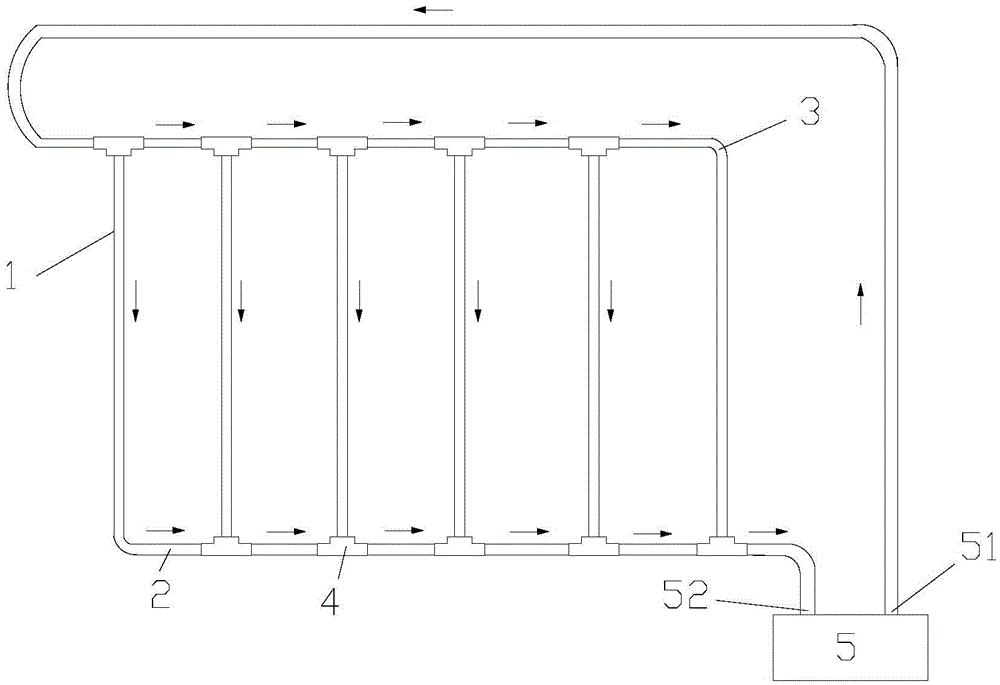
[0012] like figure 1 As shown, the embodiment of the present invention is provided with 6 radiating pipes 1, the outlet of the first radiating pipe is provided with an elbow joint 2, the inlet of the last radiating pipe is provided with an elbow joint 3, the inlet of the first radiating pipe, the last The outlet of one radiating pipe and the inlets and outlets of other radiating pipes are provided with a tee joint 4, the inlets of adjacent radiating pipes are connected through a tee joint, the outlets of adjacent radiating pipes are connected through a tee joint, and the first heat radiating pipe The heating medium inlet is connected to the refrigerant outlet 51 of the heat pump 5, and the heating medium outlet of the last heat pipe is connected to the return heating medium inlet 52 of the heat pump 5. When in use, the heat pump heat oil tank heat exchanger is set At ...


PUM


Abstract

The invention discloses a heat exchanger of an oil tank heated by a heat pump and relates to an oil tank. The heat exchanger is provided with at least two heat radiating pipes, wherein an outlet of the first heat radiating pipe is provided with an elbow joint; an inlet of the last heat radiating pipe is provided with an elbow joint; each of an inlet of the first heat radiating pipe and an outlet of the last heat radiating pipe as well as inlets and outlets of other heat radiating pipes is provided with a tee joint; inlets of the adjacent heat radiating pipes are connected through the tee joints; outlets of the adjacent heat radiating pipes are connected through the tee joints; an inlet of a heating medium of the first heat radiating pipe is connected with an outlet of a refrigerant of the heat pump; an outlet of a heating medium of the last heat radiating pipe is connected with an inlet of a backflow heating medium of the heat pump; and when being used, the heat exchanger of the oil tank heated by the heat pump is arranged at the bottom inside a tank body of the oil tank. Due to the adoption of same-stroke rectangle principle design, the circulating resistance of the heating medium is greatly reduced, meanwhile the circulating frequency is increased, and therefore, the heating efficiency is increased under the same condition.

Description

technical field [0001] The invention relates to an oil tank, in particular to a heat exchanger for a heat pump heat oil tank. Background technique [0002] The oil storage tank heating device disclosed in the prior art uses steam tube heating to heat the oil in the tank. However, the steam tube heater with this structure is a single round tube, so the heating area is very small. In addition, the heat source comes from a traditional oil-fired boiler, which obviously has a relatively low overall energy efficiency ratio. At the same time, the boiler will cause corresponding pollution to the environment when it is burned, which is also a technical problem in the existing technical conditions. [0003] Chinese patent CN2811838Y discloses a shell-type oil-water heat exchanger for electric heating heat transfer oil tank, which includes a non-pressure-bearing electric heating heat transfer oil tank body with multiple electric heating tubes in its inner cavity, through the oil pipeli...

Claims


Application Information

Patent Timeline
Patent Type & Authority Applications(China)
IPC IPC(8): F24H7/02
CPCF24H7/02
Inventor 王梅军
Owner XIAMEN HAOBENG ELECTROMECHANICAL EQUIP CO LTD
Why Eureka
Try Eureka