Compensation method for airplane aeromagnetic interference

A compensation method and interference compensation technology, applied in the field of aeromagnetic detection, can solve problems affecting the accuracy of estimation results, etc.

Active Publication Date: 2016-03-23
HARBIN INST OF TECH
View PDF4 Cites 32 Cited by
  • Summary
  • Abstract
  • Description
  • Claims
  • Application Information

AI Technical Summary

Problems solved by technology

Since the estimation process of the compensation coefficient can be regarded as a linear regression, the nature of the coefficient solution matrix will inevitably affect the accuracy of the estimation result

Method used


Image

  • Compensation method for airplane aeromagnetic interference
  • Compensation method for airplane aeromagnetic interference
  • Compensation method for airplane aeromagnetic interference

Examples


specific Embodiment approach 1

[0068] The specific embodiment one, the compensation method of a kind of aircraft aeromagnetic interference described in the present embodiment is carried out according to the following steps:

[0069] 1. Construct the matrix Δ:

[0070] The magnetic field data measured by the total field magnetometer during the calibration flight is an N×1 column vector H T , the actual geomagnetic field value is N×1 column vector H E , and the magnetic interference generated by the aircraft is an N×1 column vector H I , then there are:

[0071] h T =H E +H I (1)

[0072] Among them, only H T Obtained by direct measurement;

[0073] The ultimate goal of aeromagnetic interference compensation is to determine H E , observing the above formula, it can be found that as long as H is calculated I and change it from H T H can be obtained by subtracting from E ;

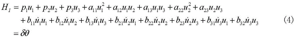
[0074] According to the T-L model, the magnetic disturbance generated by the aircraft can be expressed as:

[0075] ...

specific Embodiment approach 2

[0104] Embodiment 2. This embodiment differs from Embodiment 1 in that: the number of layers decomposed in step 2 is 9, that is, the value of j is 9. Other steps and parameters are the same as in the first embodiment.

specific Embodiment approach 3

[0105] Embodiment 3. This embodiment differs from Embodiment 1 in that: the number of layers decomposed in step 2 is 8, that is, the value of j is 8. Other steps and parameters are the same as in the first embodiment.


PUM


Abstract

The invention provides a compensation method for airplane aeromagnetic interference, relates to the field of aeromagnetic detection, and aims at solving the problem that the estimation precision of the compensation coefficient is influenced by the morbid state of a present aeromagnetic interference coefficient calculation method. The method comprises the following steps that 1) a matrix delta is constructed; 2) the matrix delta is decomposed by wavelet; 3) bandbass filtering is carried out on a result of the step 2); 4) a subscript set L is determined so that the morbid state of bpf<L>(delta) is the weakest; and 5) a compensation coefficient equation is determined to solve the compensation coefficient of aeromagnetic interference. The method provided by the invention can effectively reduce the morbid state of the coefficient solution matrix, improve the solution precision of the compensation coefficient estimation algorithm, and can be applied to the field of aeromagnetic detection.

Description

technical field [0001] The invention relates to the field of aeromagnetic detection, in particular to a compensation method for aircraft aeromagnetic interference. Background technique [0002] The aeromagnetic interference compensation technology is a technology to remove the magnetic interference of the aeronautical motion platform itself in the process of aeromagnetic detection. By analyzing the type and nature of the magnetic interference of the aviation motion platform itself, a mathematical model of the magnetic interference of the aviation motion platform is established, and then the total magnetic field and three-component data are measured according to the prescribed method during the calibration flight, and are used to calculate the air motion Coefficients of the platform magnetic interference mathematical model. In the actual aeromagnetic detection, the estimated model coefficients and aircraft attitude data are used to estimate the magnetic interference generate...

Claims


Application Information

Patent Timeline
Patent Type & Authority Applications(China)
IPC IPC(8): G01V3/16G01V3/38
CPCG01V3/16G01V3/38
Inventor 韩琦窦振家李琼牛夏牧王莘赵冠一
Owner HARBIN INST OF TECH
Why Eureka
Try Eureka