Antenna frame and antenna position control system

An antenna stand and antenna technology, applied in the direction of antenna support/installation device, antenna, antenna parts, etc., can solve the problems of antenna test signal interference, affecting test accuracy, improper positioning, etc., to reduce electromagnetic interference and increase The effect of applicability and convenient operation

Active Publication Date: 2016-03-23
GUANGZHOU CHANGEN ELECTRONICS TECH CO LTD
View PDF3 Cites 21 Cited by
  • Summary
  • Abstract
  • Description
  • Claims
  • Application Information

AI Technical Summary

Problems solved by technology

[0003] When using an open test site or an anechoic chamber for product electromagnetic compatibility testing, it is necessary to lift or rotate the antenna to change the angle of the antenna so that the test distance from the object under test to the antenna remains at a constant value; and different objects under test The volume of the antenna is different, so the distance from the antenna to the object to be measured is also different. If the existing antenna bracket is used, the distance from the antenna bracket to the object t...

Method used


Image

  • Antenna frame and antenna position control system
  • Antenna frame and antenna position control system
  • Antenna frame and antenna position control system

Examples


Embodiment 1

[0046] Embodiment 1 An antenna stand

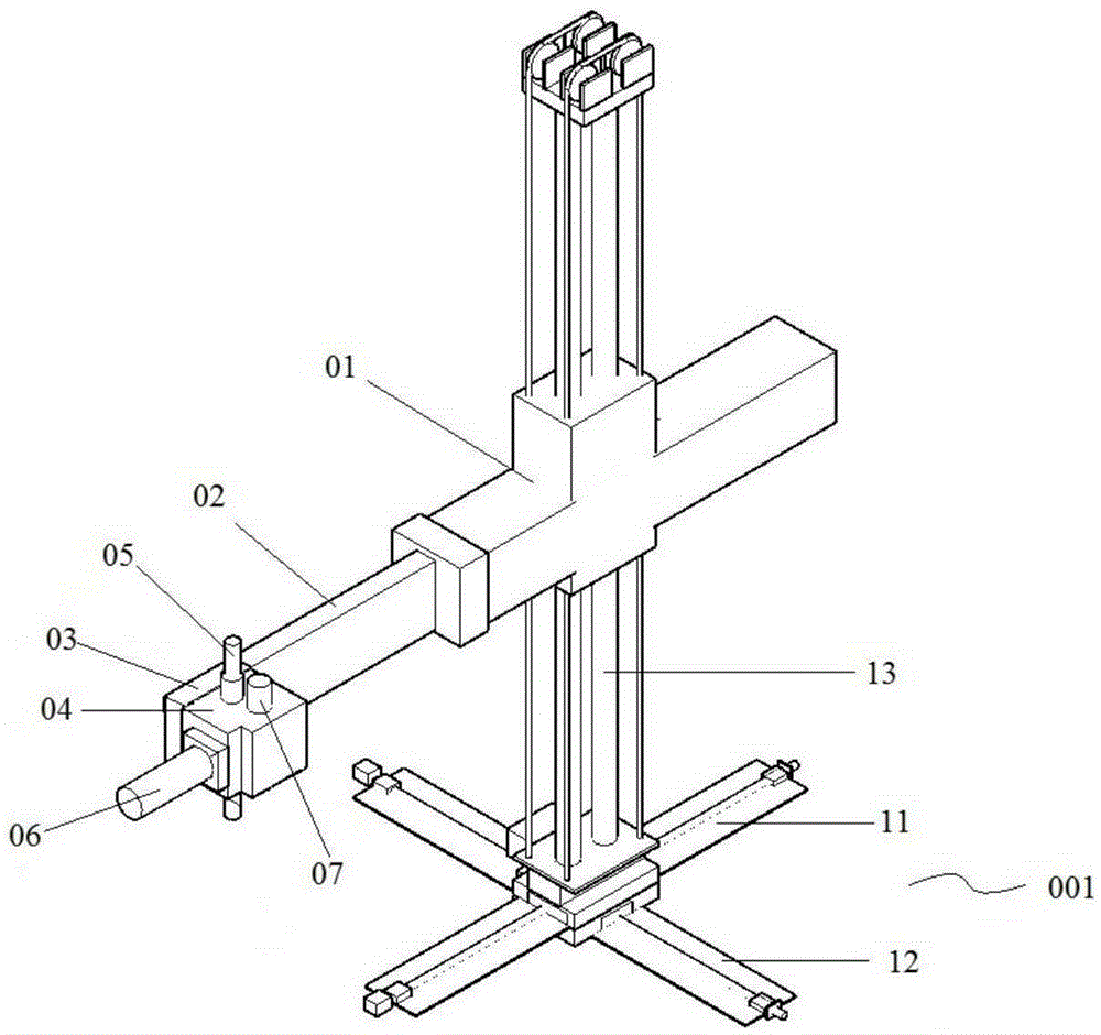
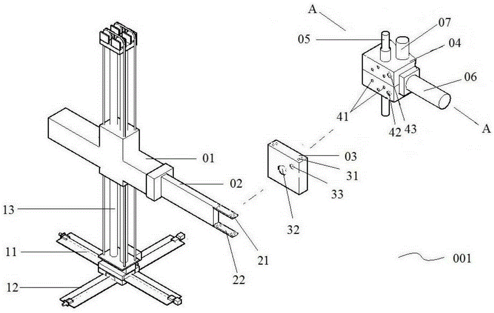
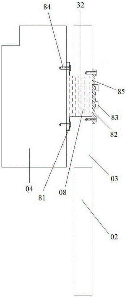
[0047] figure 1 It is a schematic structural diagram of the antenna stand 001 provided by the embodiment of the present invention; figure 2 It is an exploded schematic diagram of the structure of the antenna stand 001 provided by the embodiment of the present invention; image 3 It is a schematic diagram of the connection between the first connector 03 and the second connector 04 provided by the embodiment of the present invention.

[0048] like Figure 1-3 As shown, the antenna stand 001 provided by the embodiment of the present invention includes an antenna stand body 01, a connecting arm 02 connected to the antenna stand body 01, a first connecting member 03 fixedly connected to the connecting arm 02, and a connecting member 03 connected to the first connecting arm 02. The second connecting part 04 of the connecting part 03, the antenna 05 arranged on the second connecting part 04, the non-metallic cylinder 06 arranged on the secon...

Embodiment 2

[0117] Embodiment 2 An antenna position control system

[0118] Figure 10 is a schematic diagram of the antenna position control system provided by the embodiment of the present invention.

[0119] like Figure 10 As shown, Embodiment 2 of the present invention provides an antenna position control system 002, adopts the embodiment of the present invention to provide an antenna stand 001, and also includes a first gas-to-electricity conversion connected to the first non-metallic position sensor 07 in the antenna stand 001 device, a first position control device connected to the first gas-to-electric conversion device;

[0120] Wherein, when the second piston rod 73 of the first non-metallic position sensor 07 in the antenna frame 001 rises to the first radial air hole 7121 and the second radial air hole 7123 conduction, the first non-metallic position sensor 07 moves toward the first The gas-to-electricity conversion device sends the first air pressure signal; the first gas...


PUM


Abstract

The invention provides an antenna frame and an antenna position control system. The antenna frame provided by the invention comprises an antenna frame body, a connecting arm connected with the antenna frame body, a connecting piece fixedly connected with the connecting arm, and an antenna and a nonmetal cylinder which are arranged on the connecting piece, wherein the nonmetal cylinder can drive the antenna to perform 0-90-degree rotation. The antenna frame and the antenna position control system provided by the invention have the advantages of convenient operation and accurate positioning, can also adjust the position of the antenna frame in an X-axis direction, a Y-axis direction and a Z-axis direction, at the same time, can also control the horizontal pitch angle of the antenna and the rotation angle of the antenna, realize positioning of the antenna in multi-dimension space, and improve the applicability of the antenna frame and the antenna position control system accordingly.

Description

technical field [0001] The invention relates to supporting equipment for electromagnetic compatibility testing, in particular to an antenna frame and an antenna position control system. Background technique [0002] With the rapid development of society and economy, people pay more and more attention to the electromagnetic compatibility of products. For products included in the scope of national compulsory product certification, electromagnetic compatibility testing has become a must-test item. [0003] When using an open test site or an anechoic chamber for product electromagnetic compatibility testing, it is necessary to lift or rotate the antenna to change the angle of the antenna so that the test distance from the object under test to the antenna remains at a constant value; and different objects under test The volume of the antenna is different, so the distance from the antenna to the object to be measured is also different. If the existing antenna bracket is used, the ...

Claims


Application Information

Patent Timeline
IPC IPC(8): H01Q1/22H01Q3/34
CPCH01Q1/22H01Q3/34H01Q1/125H01Q3/08
Inventor 李楠李军
Owner GUANGZHOU CHANGEN ELECTRONICS TECH CO LTD
Why Eureka
Try Eureka