
A Miniaturized Low Frequency Omnidirectional Plate Antenna

A plate antenna, low frequency technology, applied in the direction of the structure connection of the antenna grounding switch, the structure form of the radiating element, etc., can solve the problems of the inability to meet the vertical polarization and omnidirectionality, the inability to install vertically, and the height of the antenna, and to meet the special installation requirements. requirements, increase the capacitance of the antenna, and extend the effect of the antenna bandwidth

Active Publication Date: 2019-02-26
陕西烽火诺信科技有限公司
View PDF4 Cites 0 Cited by
  • Summary
  • Abstract
  • Description
  • Claims
  • Application Information

AI Technical Summary

Problems solved by technology

[0003] Since the detachable life-saving emergency positioning system is installed or modified on the active aircraft, the volume is limited, and a miniaturized, low-profile, vertically polarized omnidirectional antenna is required, and the domestic existing 243MHz-248MHz frequency band Omnidirectional antennas are mainly whip antennas, which are very high and cannot be installed vertically inside the detachable lifesaving emergency positioning system. If they are installed horizontally, they cannot meet the requirements of vertical polarization and omnidirectionality
According to data analysis, foreign detachable lifesaving emergency positioning systems are all equipped with miniaturized, low-profile omnidirectional plate antennas. They use folding patch technology, which can produce miniaturized, low-profile, vertical polar antennas Omni-directional antenna, but the bandwidth is narrow, only about 1MHz (foreign life-saving frequency system is only 243MHz, so the bandwidth of 1MHz can meet the needs of foreign systems), far from meeting the needs of 5MHz bandwidth in the 243MHz~248MHz frequency band

Method used

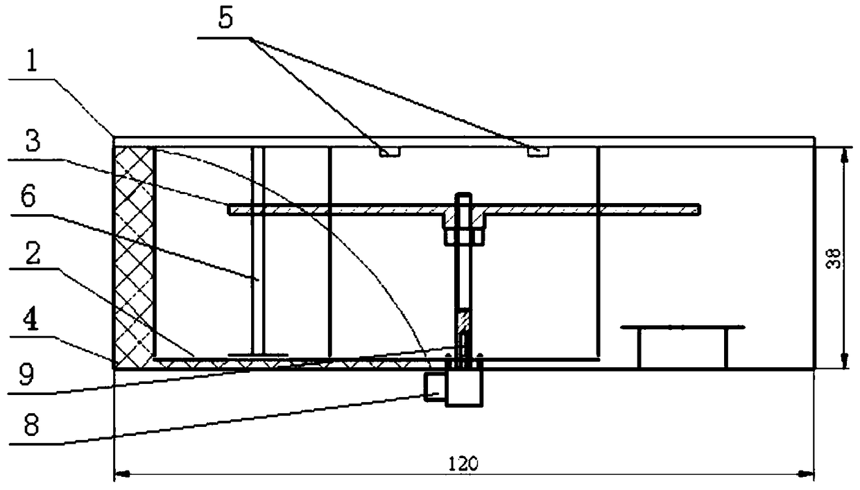

Image

  • A Miniaturized Low Frequency Omnidirectional Plate Antenna
  • A Miniaturized Low Frequency Omnidirectional Plate Antenna
  • A Miniaturized Low Frequency Omnidirectional Plate Antenna

Examples


Embodiment Construction

[0021] The structural principle and working principle of the present invention are further described below.

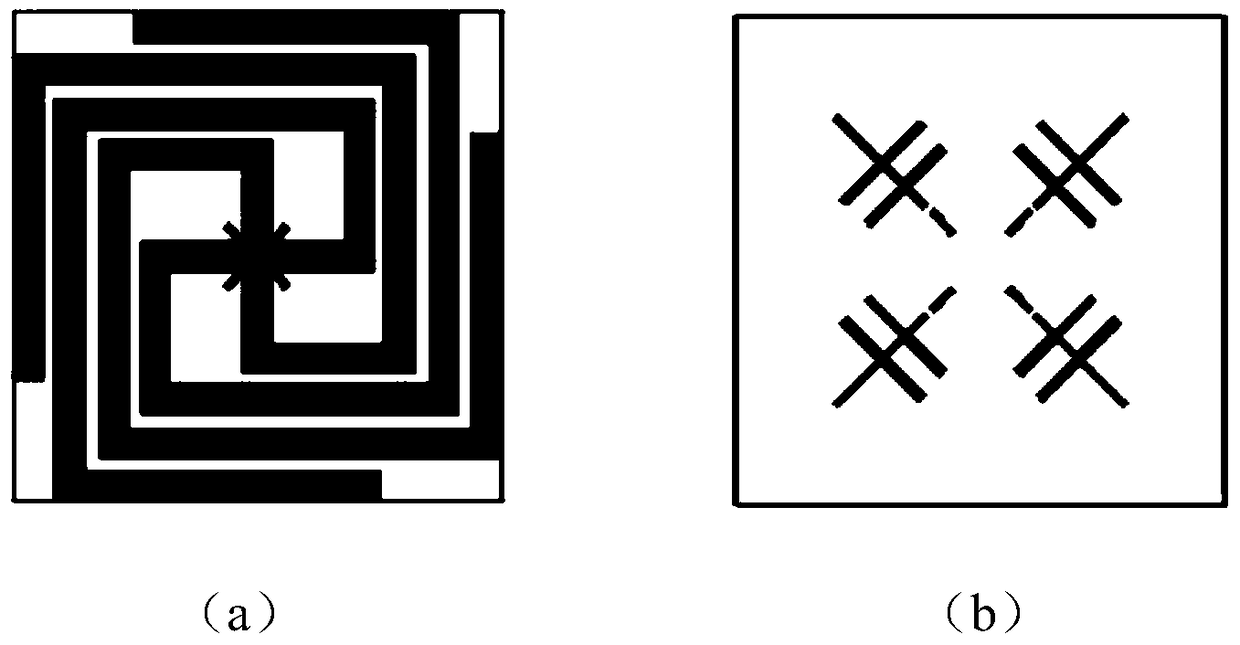
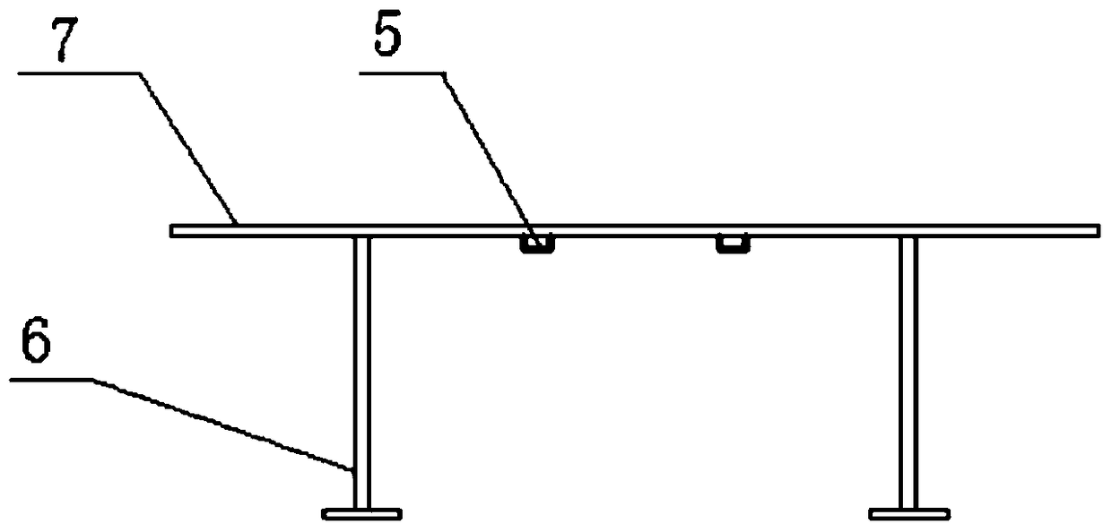
[0022] see figure 1 , figure 2 , image 3 , the present invention is a miniaturized low-frequency omnidirectional plate antenna, including a horizontally placed radiator 1, the four corners of the radiator 1 are fixed above the casing 4 by non-metallic screws, and the radiator 1 is printed by a microstrip. The board 7 is made of four-arm spiral grooves to ensure the electrical performance index of the antenna. The length, width and height of the microstrip printed board 7 are 120mm×120mm×2mm, and the metal coating of the microstrip printed board 7 is " The plane distribution of the swastika character can ensure that the antenna can work within the frequency range. Four fine-tuning resistors 5 are welded in the space reserved on the lower surface of the microstrip printed board 7. The end of the metallized part on the lower surface of the microstrip printed board 7 ...


PUM


Abstract

A miniature low-frequency omnibearing planar antenna comprises a radiating body, wherein the radiating body is horizontally arranged, four angles of the radiating body are fixed above a shell, the radiating body is formed by spirally grooving four arms of a microstrip printed board, a metal plating layer of the microstrip printed board is arranged in a Swastika emblem plane, four trimming resistors are welded in a reserved gap in the lower surface of the microstrip printed board, a tail end of a metallic part at the lower surface of the microstrip printed board is welded with one end of each of four short-connected branches, the other ends of the four short-connected branches are welded on a metal floor, the metal floor is pasted on the inner surface of the bottom surface of the shell and fixedly welded with an outer conductor, a connector is arranged on the outer surface of the bottom surface of the shell, and a feed stud is welded on an insertion needle of the connector and vertically and fixedly connected with a feed round disc. With the adoption of the feed round disc for coupling feeding, the antenna compatibility is improved; and the antenna bandwidth is effectively expanded by the four trimming resistors, so that the miniature low-frequency omnibearing planar antenna meets the requirements of a frequency band of 243 to 248 MHz and bandwidth of 5MHz and has the characteristics of small volume, low profile and vertical polarization.

Description

technical field [0001] The invention relates to an ultra-short-wave frequency band plate antenna, belonging to the technical field of antennas, in particular to a miniaturized low-frequency omnidirectional plate antenna. Background technique [0002] At present, my country's detachable life-saving emergency positioning system installed or modified for aircraft needs to be triggered and separated from the body when the aircraft is in an accident, falling to the ground or water, and sending a life-saving signal to free space. Therefore, an omnidirectional antenna capable of operating in the frequency band of 243MHz to 248MHz is required. [0003] Since the detachable life-saving emergency positioning system is installed or modified on the active aircraft, the volume is limited, and a miniaturized, low-profile, vertically polarized omnidirectional antenna is required. The omnidirectional antenna is mainly a whip antenna. This antenna is very high and cannot be installed vertic...

Claims


Application Information

Patent Timeline
Patent Type & Authority Patents(China)
IPC IPC(8): H01Q1/36H01Q1/38H01Q1/50
CPCH01Q1/36H01Q1/38H01Q1/50
Inventor 于汶涛张志云李凯赵艳高蕾
Owner 陕西烽火诺信科技有限公司
Learn More