
A t/r component testing device and device safety verification method

A component testing and component technology, applied in transmitter monitoring, receiver monitoring and other directions, can solve the problem of high construction cost of test devices, affecting device test efficiency, accuracy and repeatability, and inability to noise figure and receiving input port standing wave ratio. Testing and other issues to reduce the impact of test accuracy and consistency, improve test efficiency, and reduce construction costs

Active Publication Date: 2018-01-30
THE 41ST INST OF CHINA ELECTRONICS TECH GRP
View PDF6 Cites 0 Cited by
  • Summary
  • Abstract
  • Description
  • Claims
  • Application Information

AI Technical Summary

Problems solved by technology

[0011] The first purpose of the present invention is that if the attenuator or coupler is not dismantled at existing T / R component testing equipment, then noise figure and receiving input port VSWR cannot be tested, and once the attenuator or coupler is dismantled, It will also affect the test efficiency, accuracy and repeatability of the device, and the problem of high construction cost of the existing T / R component test device. The present invention provides a T / R component test device

Method used


Image

  • A t/r component testing device and device safety verification method
  • A t/r component testing device and device safety verification method
  • A t/r component testing device and device safety verification method

Examples


Embodiment 1

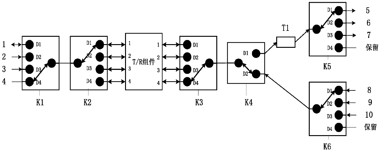
[0032] Combine Figure 1 to Figure 4 , A T / R component testing device, including a connected testing instrument, a first multi-select switch K1, a second multi-select switch K2 and a T / R component, and also a third multi-select switch K3 and a first single-pole double-throw Switch K4.

[0033] The T / R component is connected to the third multiple selection switch K3, the third multiple selection switch K3 is connected to the moving end of the first single pole double throw switch K4, and the first fixed end of the first single pole double throw switch K4 is attenuated The fourth multi-select switch K5 is connected to the transmitter or coupler T1, the fourth multi-select switch K5 is connected to the emission output test instrument, and the second fixed end of the first single-pole double-throw switch K4 is connected to the fifth multi-select switch K6, The fifth multiple selection switch is connected with a receiving input test instrument.

[0034] The detection equipment include...

Embodiment 2

[0039] The safety verification method of the T / R component testing device of the above embodiment 1 includes:

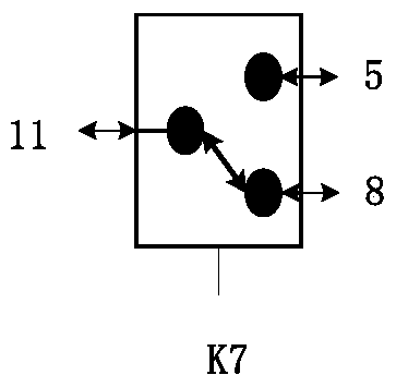
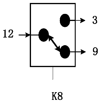
[0040] Step 1: Query the switch status, the switch status register includes S 1 , S 2 , S 3 , S 4 , S 5 , S 6 , S 7 , S 8 And S 9 , S 1 Corresponding to the first multiple selection switch K1, S 2 Corresponding to the second multiple selection switch K2, S 3 Corresponding to the third multiple selection switch K3, S 4 Corresponding to the first single-pole double-throw switch K4, S 5 Corresponding to the fourth multiple selection switch K5, S 6 Corresponding to the fifth multiple selection switch K6, S 7 Corresponding to the second single-pole double-throw switch K7, S 8 Corresponding to the third single-pole double-throw switch K8, S 9 Correspond to the fourth single-pole double-throw switch K9; different flag bits in the switch status register correspond to different positions S of each switch i D j ,Such as figure 1 As shown, the position of the first multi-selection sw...


PUM


Abstract

The invention provides a T / R component testing device and a method for checking the safety of the device. The device introduces a single-pole double-throw switch to physically separate the transmitting output channel from the receiving input channel, and an attenuator or a coupler is built into the transmitting In the output channel, this will not affect the noise figure of the receiving channel and the test of the standing wave ratio of the input port due to the large insertion loss of the channel. Compared with the existing test device, the test efficiency is improved, the influence of repeated wiring on the test accuracy and repeatability is reduced, and the number of test accessories such as attenuators or couplers is reduced, and the construction cost of the device is reduced. The integration of the device is facilitated. The safety verification of the T / R component test device before use is to query the connection state of the switch through the switch status register to ensure that the connection position of each switch is correct, and then use the low-power low-frequency excitation signal to verify the connectivity of the device to ensure When the switch fails, the test instrument will not be burned, which improves the safety of the device.

Description

Technical field [0001] The invention relates to the field of T / R component testing, in particular to a T / R component testing device and a device safety verification method. Background technique [0002] The T / R component mainly includes three parts: transmitting channel, receiving channel, and driving control. In addition, there are component interface parts such as radio frequency input and output, low-frequency connector. The transmitting channel mainly completes the amplification of the RF excitation signal and outputs it to the feeder network; the receiving channel amplifies the echo signal received by the antenna and ensures a low noise figure; the module's transceiver switch and phase and attenuation are controlled by the drive control part carry out. [0003] T / R components have the characteristics of multiple channels, coexistence of large and small power, and port multiplexing, and there are many types of indicators that require multiple test instruments to complete the t...

Claims


Application Information

Patent Timeline
Patent Type & Authority Patents(China)
IPC IPC(8): H04B17/10H04B17/20
Inventor 吴家亮丁志钊周辉公承蒋玉峰
Owner THE 41ST INST OF CHINA ELECTRONICS TECH GRP
Learn More