
High efficiency printing system for improved image quality

A high-efficiency, high-efficiency printing head technology, applied in printing devices, printing, color measurement devices, etc., can solve the problems of time-wasting materials and auxiliary equipment, and achieve the effect of reducing environmental impact and prolonging energy consumption

Active Publication Date: 2016-03-23
KODAK ALARIS INC
View PDF9 Cites 12 Cited by
  • Summary
  • Abstract
  • Description
  • Claims
  • Application Information

AI Technical Summary

Problems solved by technology

However, typical calibration procedures are time-consuming, material-intensive and require expensive auxiliary equipment

Method used


Image

  • High efficiency printing system for improved image quality
  • High efficiency printing system for improved image quality
  • High efficiency printing system for improved image quality

Examples


Embodiment Construction

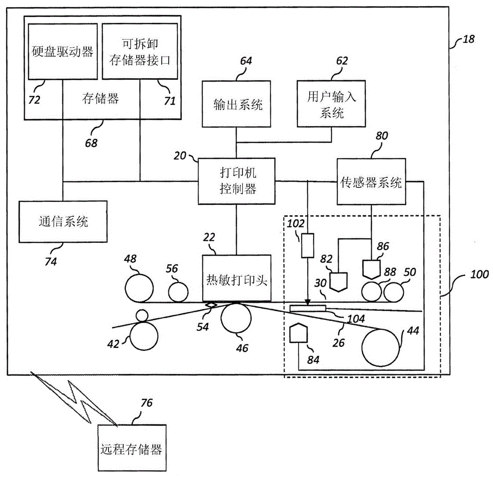
[0026] figure 1 A system diagram of an exemplary thermal printer 18 according to the present invention is shown. Such as figure 1 As shown in , a thermal printer 18 has a printer controller 20 that causes a thermal printhead 22 to record an image onto a receiver medium 26 by applying heat and pressure to transfer material from a donor ribbon 30 to the receiver medium 26 . Receiving medium 26 comprises a dye-receiving layer coated on a substrate. As used herein, the term "receiving medium" is synonymous with the terms "thermographic receiver" and "thermosensitive medium". Similarly, the term "donor ribbon" is synonymous with the terms "thermally sensitive donor" and "donor tape".

[0027] Printer controller 20 may comprise, but is not limited to, a programmable digital computer, a programmable microprocessor, a programmable logic controller, a series of electronic circuits, a series of electronic circuits reduced to an integrated circuit, or a series of discrete components...


PUM


Abstract

A high efficiency thermal printing system, comprising: a donor ribbon having donor material; a receiver medium; a test pattern to be printed on the receiver medium using the donor ribbon; a print head, a sensor, and a processor is disclosed. The present invention is adapted to print the test pattern on the receiver medium by heating the donor ribbon to cause the donor material to transfer from the donor ribbon onto the receiver medium, thereby depleting donor material on the donor ribbon. Moreover, the sensor is adapted to measure a depletion amount of the donor material on the donor ribbon after printing the test pattern, and the processor is adapted to calibrate the thermal printing system by adjusting a lookup table in response to the measured depletion amount of donor material.

Description

[0001] Cross References to Related Applications [0002] This application claims the benefit of U.S. Provisional Application No. 61 / 829,534, filed May 31, 2013, and U.S. Provisional Application No. 61 / 829,540, filed May 31, 2013. Additionally, the entire contents of both US Provisional Application Nos. 61 / 829,534 and 61 / 829,540 are hereby incorporated by reference into this application. technical field [0003] The present invention relates to the field of thermal printing systems, and more particularly, the present invention relates to methods and systems for calibrating thermal printers that provide improved image quality using high efficiency donor ribbons and receivers. The methods and systems can also be used to detect instances where inefficient donor ribbons and receivers are loaded into thermal printers. Background technique [0004] In thermal dye-sublimation printing, an image is rendered by heating one or more donor materials, such as colorants (eg, dyes) or oth...

Claims


Application Information

Patent Timeline
Patent Type & Authority Applications(China)
IPC IPC(8): B41J31/14B41J2/325B41J29/393
CPCB41J2/325B41M5/38292B41M5/38235G01J3/46B41J11/0095
Inventor 格雷戈里·J·高尔鲍茨罗伯特·F·明德勒马库斯·M·汤森
Owner KODAK ALARIS INC
Learn More