
Floating type aerating and feeding dual-purpose machine

A suspended and dual-purpose technology, which is applied in the field of fish farming, can solve the problems of affecting the walking of breeders, unfavorable feeding and growth of fish, a large amount of manpower and time, and achieves the advantages of convenient feeding, no floor space occupation, and high utilization rate. Effect

Inactive Publication Date: 2016-03-30
李福海
View PDF6 Cites 15 Cited by
  • Summary
  • Abstract
  • Description
  • Claims
  • Application Information

AI Technical Summary

Problems solved by technology

People generally feed fish by throwing food by the side of the fish pond by hand, but this kind of feeding requires a lot of manpower and time, is time-consuming, laborious, and costly, and it is impossible to feed fish in large-scale large-scale fish ponds or cages
In addition, if a feeding machine is installed beside the pond, it will not only affect the walking of the breeders, but also the feeding surface is fan-shaped, and the feeding area is small, which is not conducive to the feeding and growth of fish.

Method used


Image

  • Floating type aerating and feeding dual-purpose machine

Examples


Embodiment

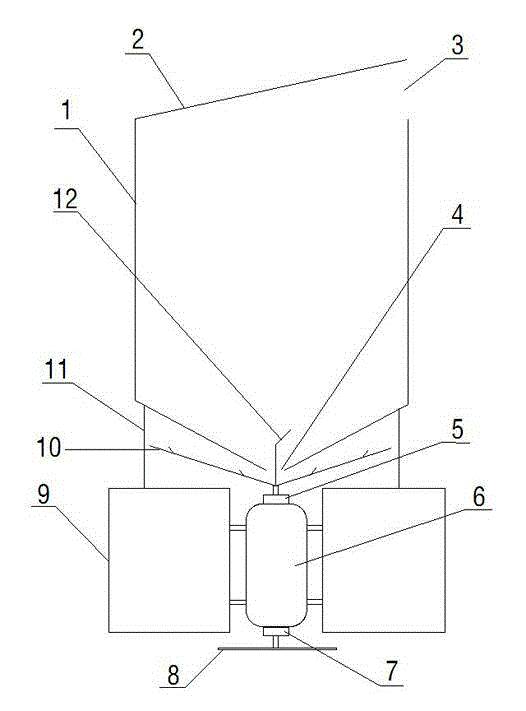
[0025] Feed box 1 and motor 6 are all fixed on the buoyancy box 9 that foam or buoyant barrel are made by fixed mount 11, and whole feeding machine is fixed on the fish pond center with rope.

[0026] The motor 6 is running, use the remote controller to combine the output shaft of the motor 6 with the remote clutch I5, the output shaft at the upper end of the motor 6 rotates, and the output shaft is connected to the feeding tray 10 through the remote clutch I5 with the remote control device to rotate, and the feeding box will be fed 1. The feed falling into the feeding tray 10 is thrown out along the parabolic path on the feeding tray 10 by centrifugal force, and the feeding process is completed; the output shaft of the motor 6 is separated from the remote control clutch I5 by the remote controller, and the feeding tray 10 stops rotating , stop feeding.

[0027] In the same way, the motor 6 is running, and the output shaft of the motor 6 is combined with the remote control clu...


PUM


Abstract

The invention relates to a floating type aerating and feeding dual-purpose machine. The floating type aerating and feeding dual-purpose machine comprises a feed box, a feed box cover, a feed inlet, a feed outlet, a remote control clutch I, a motor, a remote control clutch II, a revolving paddle, pontoons, a feeding tray, a fixing rack, a drainage connecting rod and a remote controller, wherein the motor is fixedly connected with the pontoons; the pontoons are connected with the feed box; the remote control clutch I and the remote control clutch II are separately fixed at the two ends of the motor; and the feeding tray and the drainage connecting rod are mounted on an output shaft at the upper end of the motor, and the revolving paddle is mounted on an output shaft at the lower end of the motor. According to the floating type aerating and feeding dual-purpose machine, the revolving paddle or feeding tray is conducted and driven to rotate by making full use of power of the output shafts at the two ends of the motor, so that the water surface is stirred to aerate water, or feed in the feed box is thrown out by using a centrifugal force, and the dual purposes of aerating, feeding and saving electric energy and equipment are achieved; and the utilization ratio of the equipment is increased, the cost is reduced, and the energy consumption is lowered. According to the floating type aerating and feeding dual-purpose machine, a feeding machine can float on the water surface by using the pontoons, the former sector-shaped feed throw-out is changed into circular throw-out, the area of feeding is enlarged, and the food intake for fishes is facilitated.

Description

technical field [0001] The invention relates to the field of fish farming, in particular to a suspension type dual-purpose machine for increasing oxygen and feeding. Background technique [0002] At present, ponds or net cages are the main farming methods for fish farming in rural areas, and they all extend in the shape of a well. People generally feed fish by throwing food at the edge of the fish pond by hand, but this kind of feeding requires a lot of manpower and time, is time-consuming, laborious, and costly, and it is impossible to feed fish in large-scale large-scale fish ponds or cages. In addition, if a feeding machine is installed on the side of the pond, it will not only affect the walking of the breeders, but also the feeding surface is fan-shaped, and the feeding area is small, which is not conducive to the feeding and growth of fish. Contents of the invention [0003] To sum up, the object of the present invention is to provide a dual-purpose machine for susp...

Claims


Application Information

Patent Timeline
Patent Type & Authority Applications(China)
IPC IPC(8): A01K61/02A01K63/04
Inventor 李玉良李福海
Owner 李福海
Learn More