Half-shaft separation-type reinforcement cage making equipment and use method

A steel cage and separation technology, which is applied in the field of semi-shaft separation steel cage production equipment, can solve the problems of complicated operation, time-consuming and laborious, stirrup deformation, etc.

Active Publication Date: 2016-03-30
NINGBO COMM ENG CONSTR GRP
View PDF8 Cites 14 Cited by
  • Summary
  • Abstract
  • Description
  • Claims
  • Application Information

AI Technical Summary

Problems solved by technology

The steel cage formed in this way has three defects: one is that the main reinforcement passing through the corresponding hole of the fixed rotating disk to the moving rotating disk is manually fixed, and the steel reinforcement ring of the steel cage needs to be manually moved and positioned, which is time-consuming and laborious; the other is to fix the rotating disk and move It is difficult to realize the synchronous rotation of the rotating disk, which is easy to twist the main reinforcement of the reinforcement cage; the third is that the mid-span deflection of the reinforcement cage along the length direction is too large, and it is easy to deform the wound stirrup by using the roller support
And the disclosed Chinese patent number: ZL201120384436.7, titled "a kind of reinforcement cage manufacturing equipment" although it can form a reinforcement cage at one time, it needs to lift the rotating shaft, remove the movable support, draw in the support rods, and draw out the reinforcement cage. Complex, cumbersome operation, low level of mechanization and automation

Method used


Image

  • Half-shaft separation-type reinforcement cage making equipment and use method
  • Half-shaft separation-type reinforcement cage making equipment and use method
  • Half-shaft separation-type reinforcement cage making equipment and use method

Examples


Embodiment Construction

[0109] The embodiments of the present invention will be described in detail below according to the above-mentioned drawings.

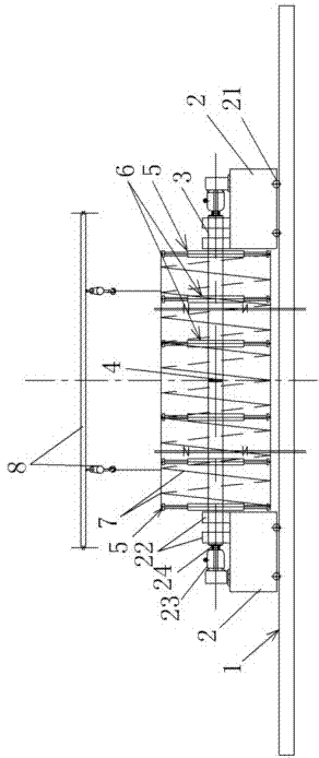
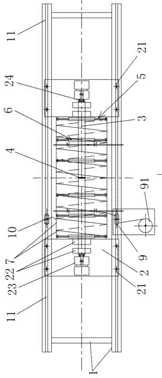
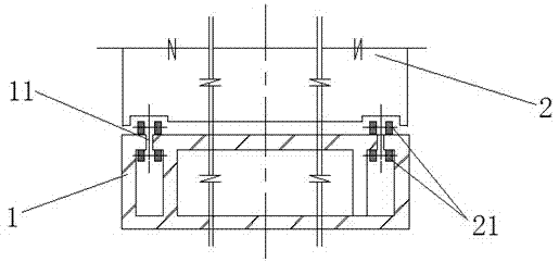
[0110] Such as Figure 1~Figure 12 As shown, 1. base, 11. chute, 2. mobile platform, 21. mobile wheel, 22. bearing, 23. motor, 24. clutch converter, 3. half shaft, 4. half shaft connector, 41. Connector bolts, 42. Connector nuts, 5. Positioning disc, 51. Positioning disc sleeve, 510. Hydraulic nozzle, 511. Sub-hydraulic pipe, 512. Sub-hydraulic ring, 513. Hydraulic tube bundle, 514. Total hydraulic pipe ring, 515. Closed middle plate, 516. Return spring, 517. Reserved hole, 518. Reserved hole bolt, 52. Disc sleeve bolt, 53. Fixed strut, 54. Movable strut, 55. Adjusting strut, 56. Positioning ring, 57. Positioning ring bolt, 58. Positioning clamp, 591. Joint sleeve, 592. Consolidation end, 593. Overhang end, 594. Joint hole, 6. Positioning support, 61. Positioning support sleeve, 62. Support Set of bolts, 7. Reinforcement cage, 71. Reinforcement ring,...


PUM


Abstract

The invention discloses half-shaft separation-type reinforcement cage making equipment and a use method. The half-shaft separation-type reinforcement cage making equipment can be used for making a reinforcement cage which is shaped like a cylinder or square tube. According to the making equipment, two mobile stations which support the reinforcement cage are each provided with a rotatable and integrally connected half shaft, each mobile station is further provided with a motor and a clutch converter which converts the output power of the motor to drive the corresponding half shaft to rotate or drive the corresponding mobile station to move axially, and multiple positioning supports which have the same numbers and positions as those of reinforcing rings of the reinforcement cage and are used for supporting main reinforcement of the reinforcement cage are additionally arranged between two positioning plates; meanwhile, corresponding improvement is conducted on positioning plate structures for supporting the main reinforcement of the reinforcement cage, the improved reinforcement cage making equipment has the advantages of being simple in structure, convenient to use, reliable in quality, economical, reasonable, high in degree of mechanization and automation, high in universality and the like, a better using effect can be achieved by matching with a corresponding use method, and higher economic benefit and social benefit are achieved.

Description

technical field [0001] The invention relates to the field of reinforcement cage construction, in particular to manufacturing equipment and a method of using a half-shaft separated type reinforcement cage. Background technique [0002] The reinforcement cage of the reinforced concrete member is welded or bound by the main reinforcement, the reinforcement ring and the stirrup. At present, the steel cage roll welding machine used in China manually fixes the main reinforcement through the corresponding template hole of the fixed rotating disk to the corresponding hole of the moving rotating disk. The disk and the moving rotating disk that rotates and moves backwards rotate to wind the stirrups on the main reinforcement and weld them at the same time to form a cylindrical or square cylindrical reinforcement cage product. The steel cage formed in this way has three defects: one is that the main reinforcement passing through the corresponding hole of the fixed rotating disk to the...

Claims


Application Information

Patent Timeline
Patent Type & Authority Applications(China)
IPC IPC(8): B21F31/00E02D5/34
CPCB21F31/00E02D5/34
Inventor 罗炎波陈军民孔庆立冯鸿登胡义辉覃坚汪金炬柳文全马前民段群苗周一勤
Owner NINGBO COMM ENG CONSTR GRP
Why Eureka
Try Eureka