Spot or projection welding method using potential difference between positive and negative electrodes

A technology of positive and negative poles and potential, applied in the direction of resistance welding equipment, welding equipment, metal processing equipment, etc., can solve the problem that the penetration depth is difficult to reach 0.2mm, achieve the deformation of the welding area, improve the penetration depth of the weld nugget, and spot welding The effect of quality improvement

Inactive Publication Date: 2016-03-30
SHANGHAI TRACTOR & INTERNAL COMBUSTION ENGINE
View PDF12 Cites 2 Cited by
  • Summary
  • Abstract
  • Description
  • Claims
  • Application Information

AI Technical Summary

Problems solved by technology

[0006] 3: In the ordinary projection welding process, the penetration depth is difficult to reach 0.2mm

Method used


Image

  • Spot or projection welding method using potential difference between positive and negative electrodes
  • Spot or projection welding method using potential difference between positive and negative electrodes
  • Spot or projection welding method using potential difference between positive and negative electrodes

Examples


Embodiment Construction

[0025] The implementation of the present invention will be illustrated by specific specific examples below, and those skilled in the art can easily understand other advantages and effects of the present invention from the contents disclosed in this specification.

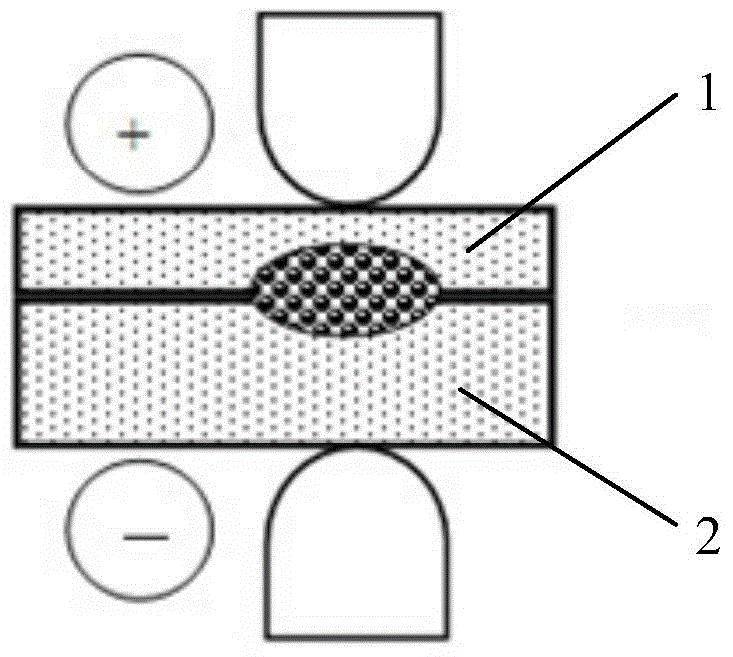
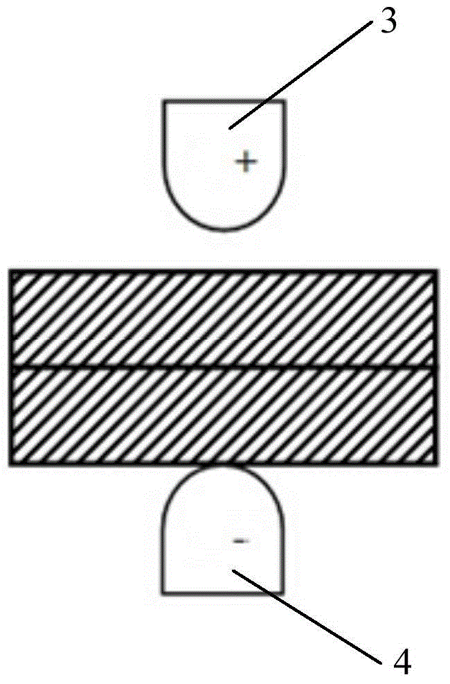
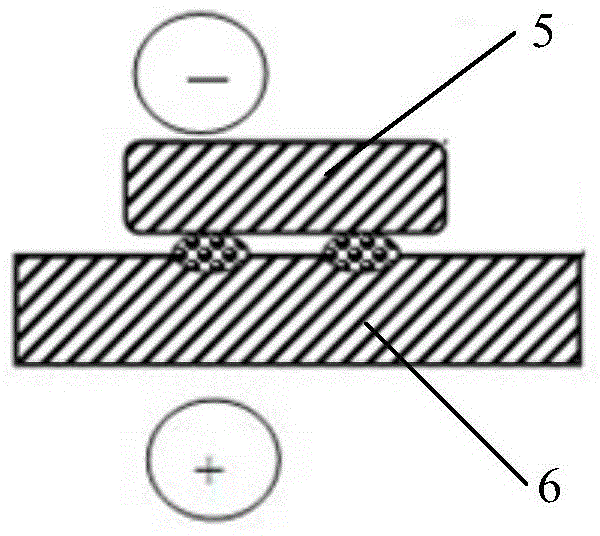
[0026] see Figure 1 to Figure 3 . It should be noted that the structures, proportions, sizes, etc. shown in the drawings attached to this specification are only used to match the content disclosed in the specification, for those who are familiar with this technology to understand and read, and are not used to limit the implementation of the present invention. Limiting conditions, so there is no technical substantive meaning, any modification of structure, change of proportional relationship or adjustment of size, without affecting the effect and purpose of the present invention, should still fall within the scope of the present invention. The disclosed technical content must be within the scope covered. At the sa...


PUM


Abstract

The invention provides a spot or projection welding method using the potential difference between positive and negative electrodes. Two layers of welding boards are clamped between two electrode arms. When the two layers of welding boards are unequal-thickness boards different in thickness, the electrode arm on the thin-board side is connected with the positive electrode of a transformer, and the electrode arm on the thick-board side is connected with the negative electrode of the transformer. When a robot is used for spot welding, the static electrode arm is connected with the negative electrode of the transformer, and the movable electrode arm is connected with the positive electrode of the transformer. During projection welding, the two layers of welding boards are a stamping part and a standard part respectively, the electrode arm on the stamping-part side is connected with the positive electrode of the transformer, and the electrode arm on the standard-part side is connected with the negative electrode of the transformer. Polarity characteristics of medium-frequency direct-current equipment are fully used, and the problem that pseudo soldering is likely to occur during spot welding of the unequal-thickness boards is solved; meanwhile, the depth of fusion of a welding core can be increased during projection welding.

Description

technical field [0001] The present invention relates to the field of welding; [0002] In particular, it relates to a spot welding or projection welding method applied to automobile body-in-white by utilizing the positive and negative potential differences of electrode arms. Background technique [0003] In the manufacture of automobile body-in-white, there are the following problems for projection welding and spot welding processes: [0004] 1: Ordinary spot welding: When the two-layer welded plates are different thickness plates or plates of different materials, it is easy to produce nugget offset, and the nugget will be asymmetrical to its interface, but to the thick plate or conduct electricity and heat. The side with poor performance is shifted. As a result of the shift, the penetration rate of thin parts or workpieces with good electrical and thermal conductivity will be reduced, and the strength of solder joints will be reduced, resulting in virtual welding. [0005...

Claims


Application Information

Patent Timeline
Patent Type & Authority Applications(China)
IPC IPC(8): B23K11/11B23K11/14
Inventor 褚卫东王大明尹福刚
Owner SHANGHAI TRACTOR & INTERNAL COMBUSTION ENGINE
Why Eureka
Try Eureka