
A compound machine for chamfering and rolling cutting of ring parts

A compound machine and ring-shaped technology, applied in other manufacturing equipment/tools, manufacturing tools, etc., can solve the problems of low processing efficiency, high input cost, and inconvenient operation, so as to improve work efficiency, reduce processing equipment, and fix the effect. Good results

Active Publication Date: 2018-05-25
嘉兴市标速汽车零部件股份有限公司
View PDF6 Cites 0 Cited by
  • Summary
  • Abstract
  • Description
  • Claims
  • Application Information

AI Technical Summary

Problems solved by technology

[0004] What the present invention solves is that the existing chamfering processing device needs to be sent to the next process for deburring after chamfering processing, so as to improve the precision of the product surface, but the existing deburring method has certain limitations, such as The operation is not convenient enough, the process is numerous, the processing efficiency is low, the repair effect is not ideal, and the input cost is high, etc.

Method used


Image

  • A compound machine for chamfering and rolling cutting of ring parts
  • A compound machine for chamfering and rolling cutting of ring parts
  • A compound machine for chamfering and rolling cutting of ring parts

Examples


Embodiment Construction

[0021] The present invention will be further described below in conjunction with drawings and embodiments.

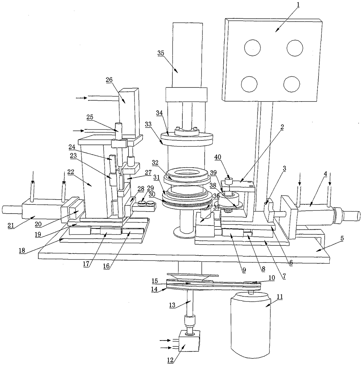
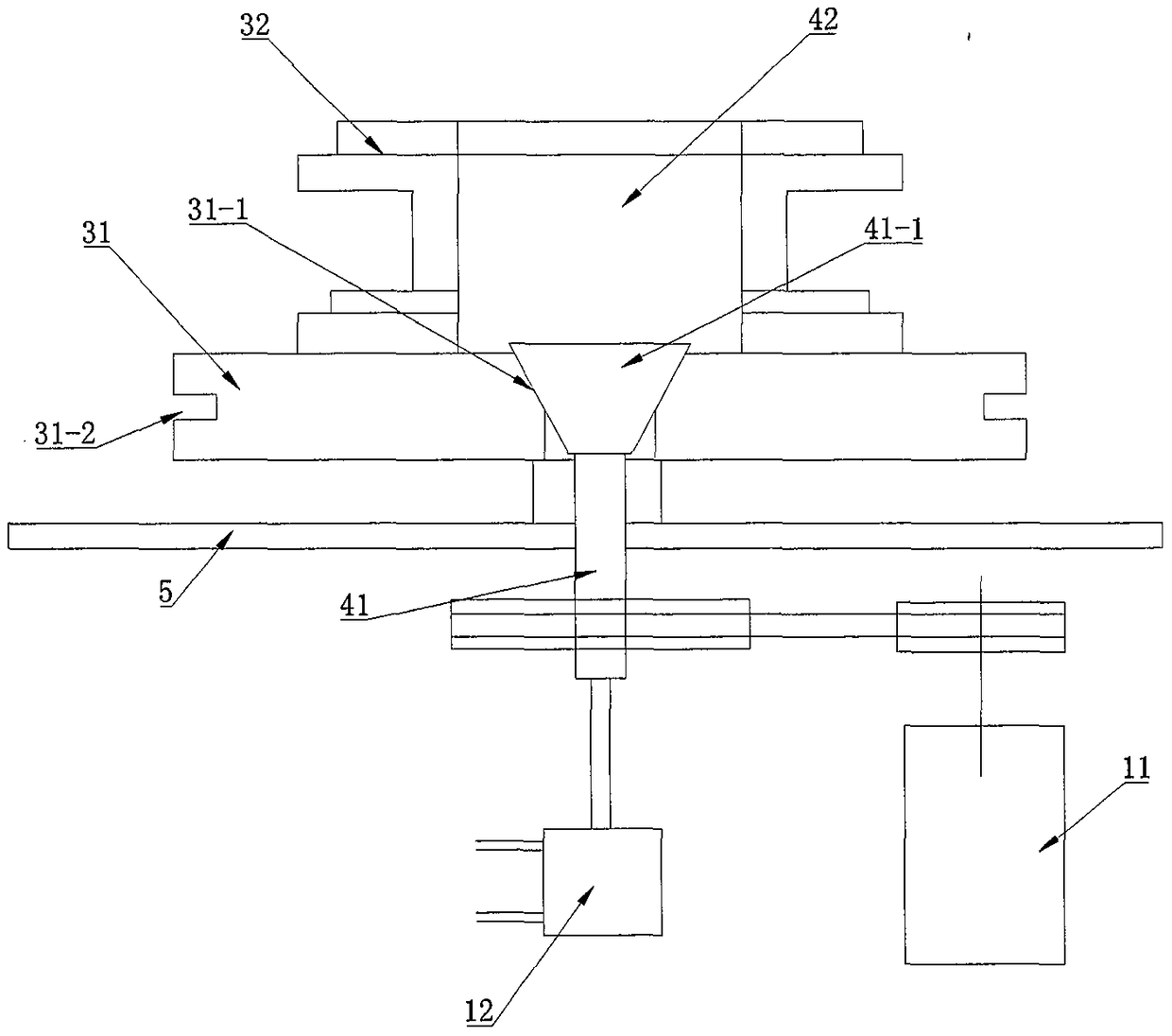
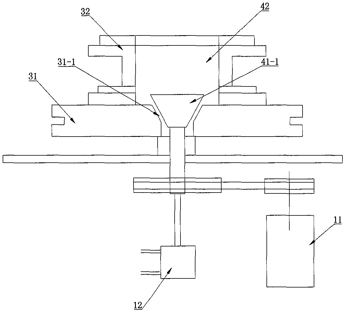
[0022] Such as figure 1 and figure 2 Shown, the present invention comprises workbench 5, control panel 1 and the hemming mechanism that is installed on the workbench successively from left to right, main power mechanism and trimming mechanism. The control panel 1 is electrically connected with the main power mechanism, the trimming mechanism and the hemming mechanism respectively. The control panel 1 is used to control the orderly work of the main power mechanism, the trimming mechanism and the hemming mechanism.

[0023] The active power mechanism includes a power source, an installation platform connected with the power source and installed on the workbench, and a pressing component located above the installation platform. The power source includes a motor 11 , a driving wheel 10 , a driven wheel 14 , a second cylinder 12 and a transmission shaft 41 . One end of ...


PUM


Abstract

The invention discloses a chamfering and rolling-cutting compound machine for annular elements. The chamfering and rolling-cutting compound machine comprises a workbench, a control panel as well as an edge-rolling mechanism, a main power mechanism and an edge-cutting mechanism which are sequentially installed on the workbench from left to right, and electrically connected with the control panel, wherein the main power mechanism comprises a power source, an installation platform connected with the power source and installed on the workbench, and a pressing assembly located above the installation platform; the edge-cutting mechanism comprises a cutter assembly, a first slide assembly and a first hydraulic cylinder; the cutter assembly is installed on the first slide assembly, and the first hydraulic cylinder is installed at one side of the first slide assembly; the edge-rolling mechanism comprises a rolling assembly, a second slide assembly and a first cylinder; the rolling assembly is installed on the second slide assembly, and the first cylinder is installed at one side of the second slide assembly. The chamfering and rolling-cutting compound machine disclosed by the invention is capable of completing the procedures of chamfering and trimming during an edge-rolling process, thus increasing production efficiency, and simplifying machining equipment.

Description

technical field [0001] The invention relates to a processing device for chamfering, in particular to a compound machine for chamfering and rolling cutting of ring parts. Background technique [0002] The edge of the existing circular products needs to be sent to the chamfering machine for chamfering after edge trimming. After chamfering, there will inevitably be burrs. In order to remove the surface burrs and improve the accuracy of the product surface, it is necessary to The product is sent to the next trimming and deburring process. Although there are many existing trimming and deburring methods, there are manual deburring methods such as steel files, sandpaper, grinding heads, and brushes, chemical deburring methods using electrochemical reactions, and electrolytic deburring methods. etc., but these methods have certain limitations, such as inconvenient operation, numerous procedures, low processing efficiency, unsatisfactory repair effect, and high input cost. Content...

Claims


Application Information

Patent Timeline
Patent Type & Authority Patents(China)
IPC IPC(8): B23P23/02
CPCB23P23/02
Inventor 金德
Owner 嘉兴市标速汽车零部件股份有限公司
Learn More