Built-in nails

A self-contained, nail-shooting technology, applied in nailing tools, manufacturing tools, etc., can solve the problems of high labor intensity, high dud rate, hidden safety hazards, etc., to increase the convenience of use, prolong the shelf life, and the explosion speed. quick effect

Active Publication Date: 2017-05-17
启东赫子新材料有限公司
View PDF6 Cites 0 Cited by
  • Summary
  • Abstract
  • Description
  • Claims
  • Application Information

AI Technical Summary

Problems solved by technology

[0002] Nails have been widely used in people's lives. When installing equipment, facilities, and components on high-strength building substrates (including steel), nail firing devices are usually used to fire nails, and the nails are driven into the building substrate. During the operation, the nail bullets and the nails are separately loaded into the nail firing device. The nail bullets in this way are easy to be used for other purposes, and the transportation and daily safety management requirements are high, the operation is complicated, the labor intensity is high, and the efficiency is low. noisy
Another form is that the nail-shooting device directly fires shellless pills (tablets) to drive the nails into the building matrix. This form brings serious safety hazards to transportation and daily safety management. The moisture-proof problem cannot be solved. Dud bombs Very high rate, impractical and uneconomical

Method used


Image

  • Built-in nails
  • Built-in nails
  • Built-in nails

Examples


Embodiment 1

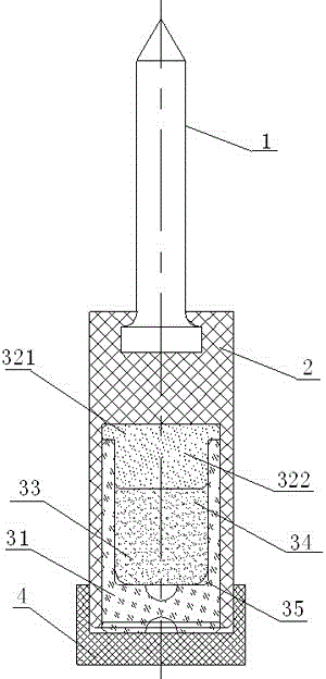
[0020] like Figure 1 to Figure 3 As shown, the self-contained nail can be used, including the nail body 1, the nail bearing housing 2 and the kinetic energy component. One end of the nail bearing housing 2 is provided with a nail cap accommodation cavity, and the nail cap of the nail body 1 is embedded in the nail. Inside the cap accommodating chamber, the other end is provided with a kinetic energy component installation chamber 21 , and the tail of the nail-shooting bearing housing 2 is provided with a safety rear cover 4 .

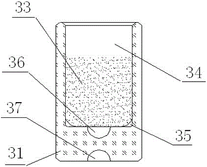
[0021] The kinetic energy assembly includes a kinetic energy mother shell 31 with an inner cavity 34, a T-shaped sealing cover 32, and a kinetic energy agent 33. A primer 36 is placed at the bottom of the kinetic energy mother shell 31, and a kinetic energy agent 33 is placed in the inner cavity 34. The 31 tail of the kinetic energy mother shell is provided with The firing pin guide hole 37, the T-shaped sealing cover 32 and the inner cavity 34 of the ...

Embodiment 2

[0025] like Figure 4 and Figure 5 As shown, in the above-mentioned embodiments, the use of solid primer powder has the disadvantages of complicated process, high requirements, high risk in the production process, and loud explosion sound during use, but when using dry powder primer powder as the primer, the explosion speed is fast and the explosion noise is small , so on the basis of Embodiment 1, the kinetic energy shell (kinetic energy mother shell 31) in the kinetic energy assembly is changed as follows to obtain an improved self-energy nailing: the kinetic energy shell includes an inner cavity with a first cavity 391 The shell 39 and the outer shell 38 with the second cavity 381, the middle of the bottom of the first cavity 391 of the inner shell 39 is provided with a detonation port 392, and the bottom of the second cavity 381 of the shell 38 is for placing the primer 36 (preferably dry powder powder) The arc-shaped groove 382, ​​the tail of the shell 38 is provided wi...


PUM


Abstract

The invention discloses a self-energizing nail. The self-energizing nail comprises a nail body, a nail bearing shell and a kinetic energy assembly; a nail head accommodating cavity is formed in one end of the nail bearing shell; a nail head of the nail body is embedded in the nail head accommodating cavity; a kinetic energy assembly mounting cavity is formed in the other end of the nail bearing shell; the kinetic energy assembly comprises a kinetic energy shell, a T-shaped sealing cover and a kinetic energy agent; the T-shaped sealing cover is in close fit with the kinetic energy shell; and the kinetic energy agent is placed in the kinetic energy shell. The self-energizing nail has the advantages of light weight, moisture prevention, safe transportation, fast assembly and not easy demounting, high firing rate, and high nail strength and rigidity.

Description

technical field [0001] The invention relates to the field of construction equipment, in particular to a self-contained energy-driven nail. Background technique [0002] Nails have been widely used in people's lives. When installing equipment, facilities, and components on high-strength building substrates (including steel), nail firing devices are usually used to fire nails, and the nails are driven into the building substrate. During the operation, the nail bullets and the nails are separately loaded into the nail firing device. The nail bullets in this way are easy to be used for other purposes, and the transportation and daily safety management requirements are high, the operation is complicated, the labor intensity is high, and the efficiency is low. Noisy. Another form is that the nail-shooting device directly fires shellless pills (tablets) to drive the nails into the building matrix. This form brings serious safety hazards to transportation and daily safety managemen...

Claims


Application Information

Patent Timeline
Patent Type & Authority Patents(China)
IPC IPC(8): B25C1/10B25C1/18
CPCB25C1/10B25C1/18
Inventor 浦丹熠钟志勇
Owner 启东赫子新材料有限公司
Why Eureka
Try Eureka