
Left foot braking and left-hand driving automatic-transmission automobile

A technology of automatic transmission and automobile, which is applied to the layout of foot-operated starting devices, vehicle components, and power plant control mechanisms. It can solve problems such as acceleration, and achieve the effects of reducing reaction time, improving driving experience, and convenience and safety.

Inactive Publication Date: 2016-03-30
程学勇
View PDF8 Cites 2 Cited by
  • Summary
  • Abstract
  • Description
  • Claims
  • Application Information

AI Technical Summary

Problems solved by technology

[0003] The technical problem to be solved by the present invention is to provide a left-hand braked left-hand driving automatic transmission car, which moves the traditional right-side brake pedal to the left side, and By installing a clutch between the brake pedal and the accelerator pedal to form a linkage under specific conditions, that is, the engine accelerates when the accelerator pedal is single-pressed, once the brake pedal is stepped on, the accelerator pedal will immediately fail and the engine will return to idle speed until the brake pedal and the accelerator pedal At the same time, the function of the accelerator pedal is restored when it is reset, which not only solves the contradiction of possible acceleration while braking, but also greatly reduces the car accidents caused by problems such as reaction time, emergency panic, and uneven severity, and also avoids the imbalance of the feet after long-distance driving. problem, improve the driving experience

Method used


Image

  • Left foot braking and left-hand driving automatic-transmission automobile
  • Left foot braking and left-hand driving automatic-transmission automobile

Examples


Embodiment Construction

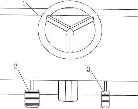
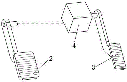
[0011] As shown in the figure, a left-hand braked left-hand driving automatic transmission car is composed of an automatic transmission car body 1, a brake pedal 2, an accelerator pedal 3 and a claw clutch 4. The brake pedal 2 is located on the left side of the steering wheel, and is composed of The driver's left foot controls, and controls whether the accelerator pedal 3 works through the claw clutch 4. When the brake pedal 2 is stepped on, the accelerator pedal 3 cannot work no matter what position the accelerator pedal 3 is in. The engines are all in an idle state. When the brake pedal 2 and the accelerator pedal 3 are reset simultaneously, the accelerator pedal 3 normally controls the engine speed, and the brake pedal 2 is transmitted to the claw clutch 4 by mechanical or hydraulic means. control separation and combination, the accelerator pedal 3 and the claw clutch 4 are linked by mechanical connection, after the claw clutch 4 is separated, only when the brake pedal 2 and...


PUM


Abstract

The invention discloses a left foot braking and left-hand driving automatic-transmission automobile. The left foot braking and left-hand driving automatic-transmission automobile mainly comprises an automatic-transmission automobile main body, a braking pedal, an accelerating pedal and a claw clutch, wherein the braking pedal is positioned on the left side of a steering wheel and controlled by the left foot of a driver; whether the accelerating pedal works or not is controlled by the claw clutch; after being separated, the claw clutch is recombined only when the braking pedal and the accelerating pedal simultaneously return; and any one of the braking pedal and the accelerating pedal does not return, the claw clutch cannot be combined. According to the invention, as the traditional braking pedal on the right side is moved to the left side and the clutch is additionally arranged between the braking pedal and the accelerating pedal so as to form linkage under a specific condition, a contradiction problem that acceleration may be caused during braking is solved, accidents caused by problems of response time, hurry and confusion, uneven loads and the like are greatly reduced, and driving experience is also improved. The left foot braking and left-hand driving automatic-transmission automobile is inevitably convenient for most drivers to safely and comfortably drive the automobiles today and tomorrow with automatic-transmission automobiles as mainstream.

Description

technical field [0001] The invention relates to an automatic transmission vehicle, in particular to a left-side driving automatic transmission vehicle with a left foot brake. Background technique [0002] At present, automatic transmission vehicles are gradually becoming people's first choice. Because of their advantages such as low technical requirements, easy operation and good handling, they will definitely become the mainstream in the near future. However, the accelerator pedal and brake pedal inherited from manual transmission vehicles are the same. This has brought about a series of problems, especially in recent years with the rapid increase in the number of drivers, a large number of mediocre drivers mistakenly use the accelerator pedal as the brake pedal, causing disasters to occur again and again. To the driver on the brake pedal, the time from when the brain sends out the brake command to when the human foot is lifted, shifted, and stepped on also greatly increase...

Claims


Application Information

Patent Timeline
IPC IPC(8): B60T7/06B60K26/02
Inventor 程学勇姬志刚姬志强贾海亮
Owner 程学勇
Learn More