Windshield device, and cool airflow device for saddle ride type vehicle

Inactive Publication Date: 2008-08-07
HONDA MOTOR CO LTD
View PDF4 Cites 15 Cited by
  • Summary
  • Abstract
  • Description
  • Claims
  • Application Information

AI Technical Summary

Benefits of technology

[0009]In view of the above, it is a first object of the present invention to obtain an enhanced screen effect and an enhanc

Problems solved by technology

However, even where such a configuration is adopted, when the outside air temperature is high, the temperature of th

Method used


Image

  • Windshield device, and cool airflow device for saddle ride type vehicle
  • Windshield device, and cool airflow device for saddle ride type vehicle
  • Windshield device, and cool airflow device for saddle ride type vehicle

Examples


first embodiment

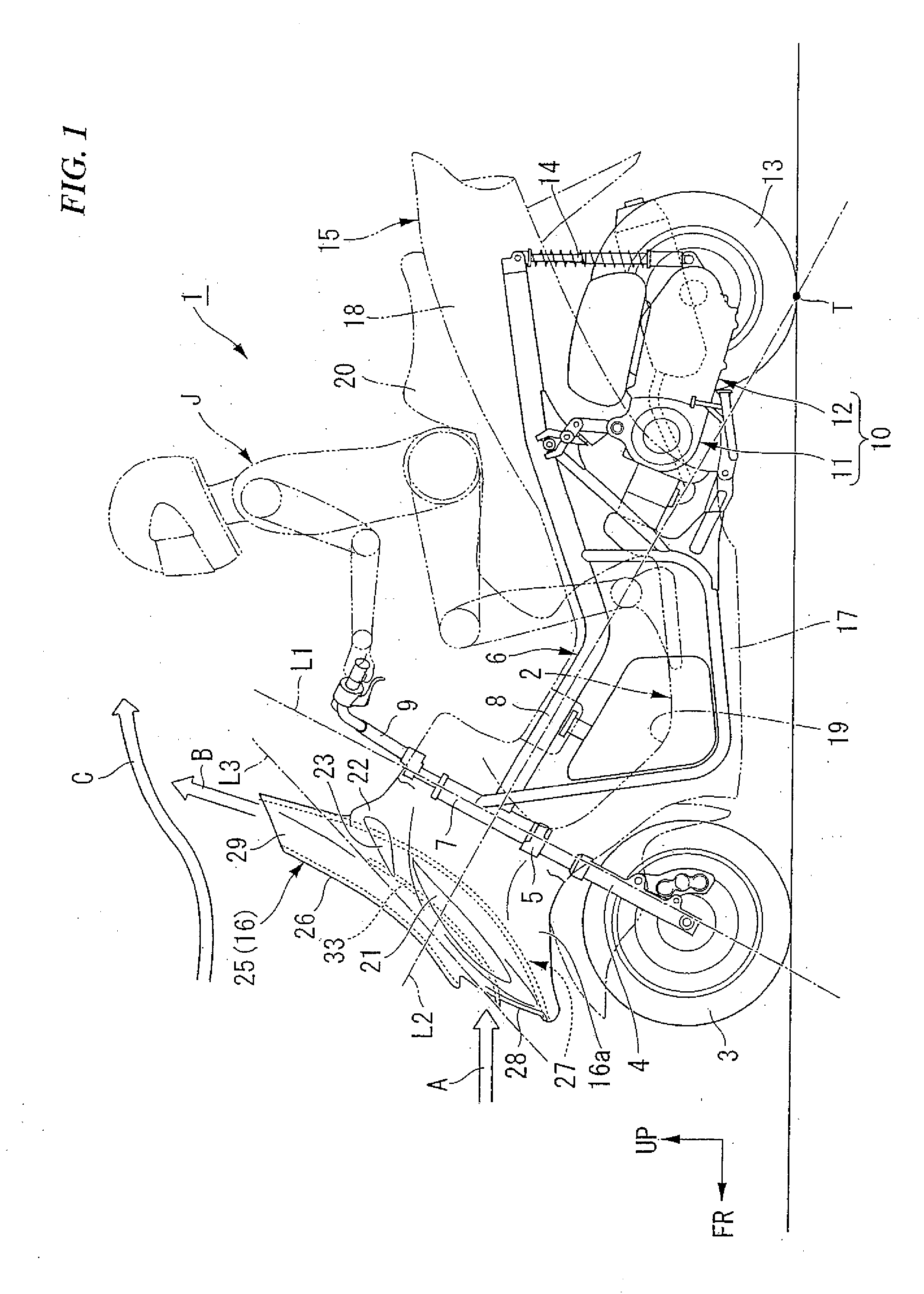
[0064]A motorcycle 1 shown in FIG. 1 is a motor scooter type vehicle having a low-level floor 2, for example. A front wheel 3 is rotatably supported on a telescopic type front fork 4. The front fork 4 is steerably supported on a head pipe 7 at a front end part of a vehicle body frame 6 through a steering stem 5.

[0065]Symbol L1 in FIG. 1 identifies a steering turning axis (steering axis), which is also the center axis of the head pipe 7. An axis along the extending / contracting direction of the front fork 4 and the steering axis L1 are parallel to each other.

[0066]The vehicle body frame 6 has a main pipe 8 that extends rearwardly downwards from the head pipe 7, is then bent, and further extends rearwardly upwards. A steering handle 9 is attached to an upper end part of the steering stem 5.

[0067]A swing unit 10 is turnably supported on a rear part of the vehicle frame 6 so that it can swing about the front end side thereof. The swing unit 10 has an engine 11 and a power transmission me...

second embodiment

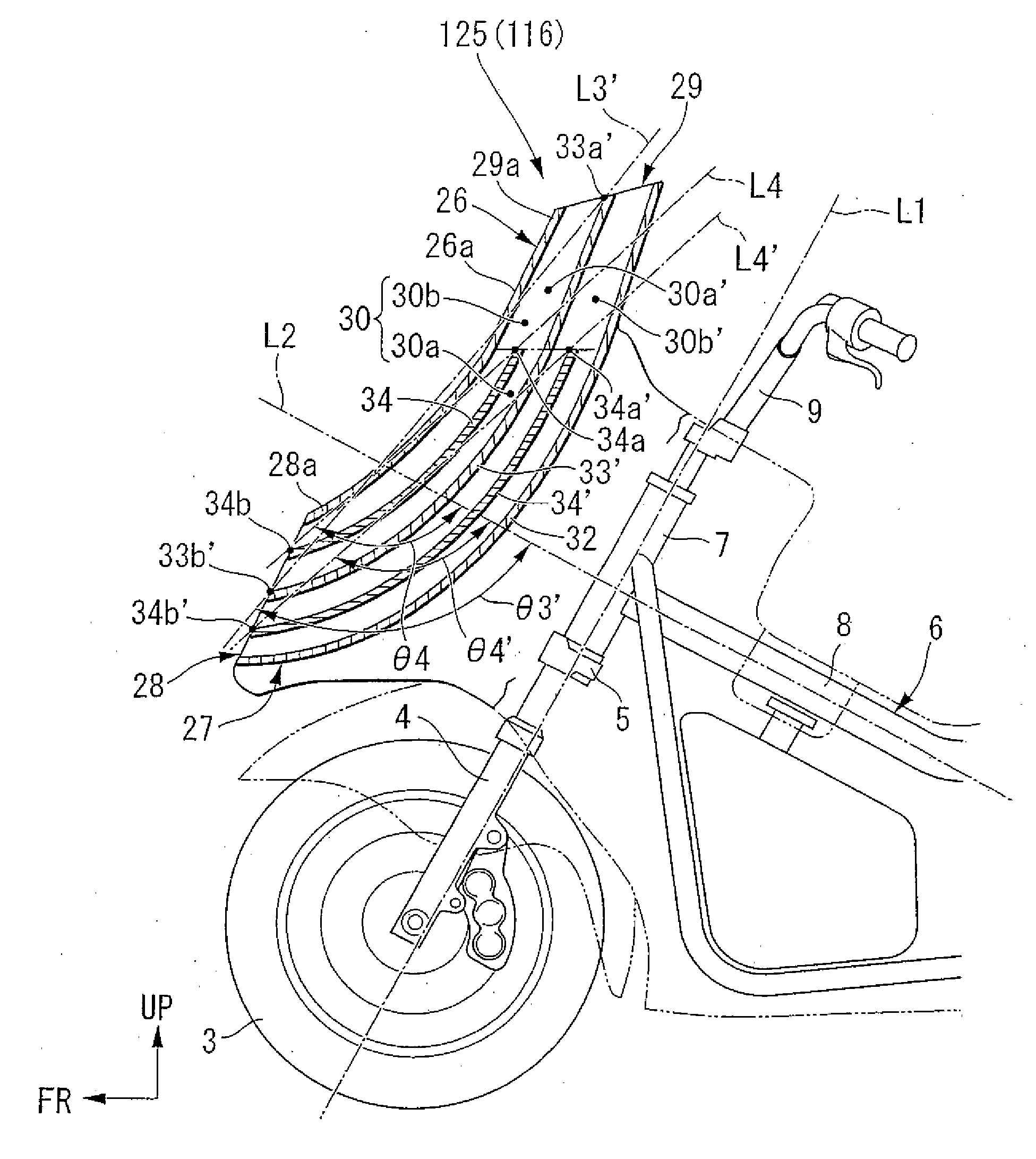
[0096]Now, a second embodiment of the present invention will be described below, referring to FIGS. 1 and 5.

[0097]A front cover 116 (screen 125) in this embodiment differs from that of the first embodiment above mainly in that a straightening vane 33′ ranging continuously over the entire length of an air passage 30 (namely, ranging from an air introduction port 28 to an air blow-off port 29) is provided in place of the above-mentioned straightening vane 33. Auxiliary straightening vanes 34, 34′ are provided in the air passage 30, respectively, on the face side and the back side of the straightening vane 33′. The same parts as those in the first embodiment above are identifies by the same symbols as used above, and descriptions of them will be omitted.

[0098]The straightening vane 33′ is provided to extend from the air introduction port 28 to the air blow-off port 29, along a screen body 26 and a rear wall part 32. The straightening vane 33′ bisects the entire space of the air passage...

third embodiment

[0108]Now, a third embodiment of the present invention will be described below, referring to the drawings. The front, rear, left and right sides and directions in the following description are the same sides and directions as those in the vehicle, unless otherwise specified. In addition, arrow FR in the drawings indicates the front side of the vehicle, arrow LH indicates the left side of the vehicle, and arrow UP indicates the upper side of the vehicle.

[0109]A motorcycle 201 shown in FIG. 6 is a motor scooter type vehicle having a low-level floor 202, for example. A front wheel 203 is rotatably supported on a telescopic type front fork 204, and the front fork 204 is steerably supported on a head pipe 207 at a front end part of a vehicle body frame 206 through a steering stem 205. The vehicle body frame 206 has a main pipe that extends rearwardly downwards from the head pipe 207, is then bent, and further extends rearwardly upwards. A steering handle 209 is attached to an upper end p...


PUM


Abstract

A windshield device provided at a front part of a vehicle body of a saddle ride type vehicle includes an air introduction port provided at a front part of the windshield device and opened toward the front side of the vehicle body. An air blow-off port is provided at an upper part of the windshield device and is opened toward the upper side. An air duct establishing communication between the air introduction port and the air blow-off port through an air passage extends rearwardly upwards. A straightening vane extends sideways in the air passage and is inclined rearwardly upwards so as to be along the air passage. In side view of the vehicle, a first straight line connecting both ends of the straightening vane is disposed at an obtuse angle in relation to a second straight line that is orthogonal to a steering axis and extends to a grounding point of a rear wheel.

Description

CROSS-REFERENCE TO RELATED APPLICATIONS[0001]This nonprovisional application claims priority under 35 U.S.C. § 119(a) on Patent Application Nos. 2007-026776, 2007-026777 and 2007-026778, each application filed in Japan on Feb. 6, 2007. The entirety of each of the above-identified applications is incorporated herein by reference.BACKGROUND OF THE INVENTION[0002]1. Field of the Invention[0003]The present invention relates to a windshield device covering a front part of a vehicle body of a saddle ride type vehicle such as a motorcycle. The present invention also relates to a cool airflow device utilizing the running airflow in a saddle ride type vehicle such as a motorcycle.[0004]2. Background of the Invention[0005]A windshield device in the background art has been proposed, in which an air blow-off port that is opened to the upper side is provided at an upper end part of a portion supporting both sides of the screen (refer to, for example, Japanese Patent Laid-open No. Sho 64-001671)....

Claims


Application Information

Patent Timeline
IPC IPC(8): B62J17/04
CPCB62J17/04B62J17/10
Inventor MATSUO, HISASHISHIDA, EMIOKUBO, TAKEFUMI
Owner HONDA MOTOR CO LTD
Why Eureka
Try Eureka