Electromagnetic shock absorber

a shock absorber and electromagnet technology, applied in the direction of shock absorbers, mechanical equipment, transportation and packaging, etc., can solve the problems of difficult control of damping force, disadvantageous in respect of costs, complex structure, etc., and achieve the effect of low cost and repair of breakdown

Inactive Publication Date: 2005-09-29
KYB CORP +1
View PDF9 Cites 17 Cited by
  • Summary
  • Abstract
  • Description
  • Claims
  • Application Information

AI Technical Summary

Benefits of technology

[0028] An advantage of the present invention is to provide an electromagnetic shock absorber which is capable of restraining the influence that moment of inertia of a rotor of a motor exercises on damping force and which is capable of making vehicles more comfortable to drive and promptly controlling the damping force according to the traveling conditions in the case that the shock absorber is applied to the suspension of a vehicle.
[0029] A further advantage of the present invention is to provide an electromagnetic shock absorber being capable of preventing a motor from being subjected to damage, as much as possible, which may arise resulting from calorification of the motor and enabling repair of breakdown at a low cost.
[0030] In order to achieve the advantages described above, the electromagnetic shock absorber according to the present invention comprises: a shock absorber body which makes telescopic motion in response to an input from outside; a ball screw mechanism which is arranged at the shock absorber body, converts the telescopic motion into rotary motion, and is composed of a ball nut and a screw shaft; a motor which is provided at the shock absorber body and generates electromagnetic resistance to oppose against rotations to be input into a rotary shaft of the motor; and a power transmitting section having an elastic body which transmits rotary motion of the ball screw mechanism to the rotary shaft of the motor and also shifts a transmission phase of the rotary motion when rotation torque of the rotary motion is changed.
[0031] Further, it is preferable to have constitution such that at least a part of the power transmitting section includes a torsion bar.
[0032] The torsion bar is constituted such that the torsion bar will break if the above-mentioned rotary torque to be transmitted is greater than a prescribed value.
[0034] projections provided at the power transmitting section are constituted such that the projections will break if the above-mentioned rotation torque to be transmitted is greater than a prescribed value.

Problems solved by technology

However, in such a suspension unit in which magnet coils are built in a hydraulic shock absorber, a hydraulic pressure, a power source, and the like are required, whereby it is complicated in structure and it is disadvantageous in respect of the costs.
However, with respect to an electromagnetic shock absorber constituted such that the screw shaft 46 is directly connected with the rotary shaft 51 of the motor 50 by the coupling 55 and the rotary motion of the shaft 46 is transmitted to the motor 50, it is feared that the following problems may arise if the electromagnetic shock absorber is actually applied to a vehicle.
Especially, referring to the electromagnetic shock absorber's controllability over damping force, it is difficult to control the damping force which arises resulting from the moment of inertia of the rotor of the motor closely relevant to the acceleration of telescopic motion of the above-mentioned shock absorber.
This will lead to the deterioration of insulation performance.
As a result, it is feared that electric leakage may occur and the motor itself may be damaged.

Method used


Image

  • Electromagnetic shock absorber
  • Electromagnetic shock absorber
  • Electromagnetic shock absorber

Examples


first embodiment

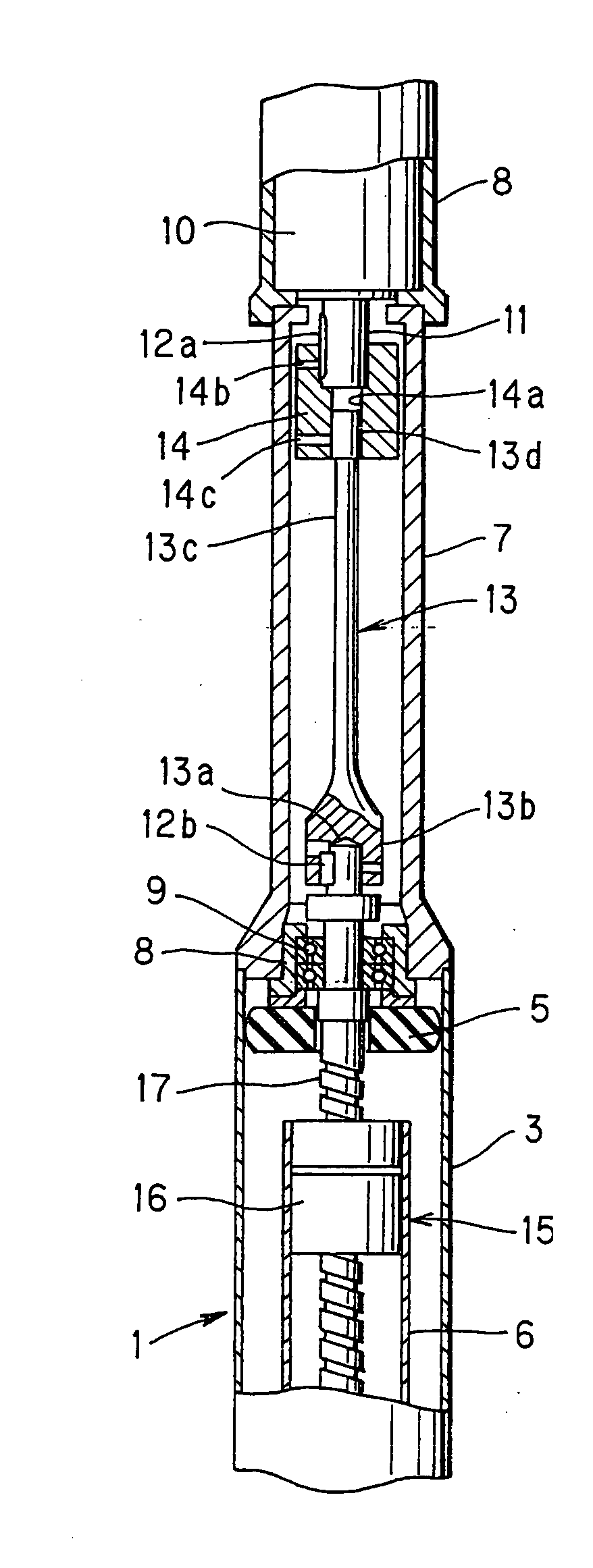
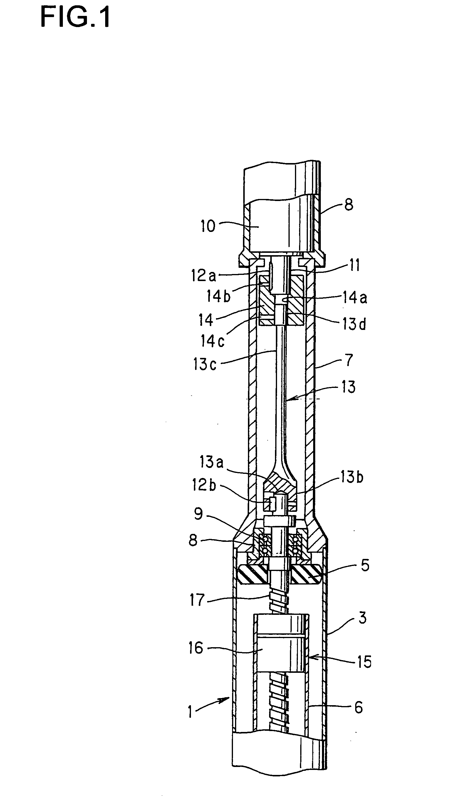
[0045]FIG. 1 is a sectional view showing an electromagnetic shock absorber according to a

[0046] A shock absorber body 1 has an external cylinder 3 and an internal cylinder 6 which is coaxially inserted in the external cylinder 3 in such a manner that the internal cylinder 6 can freely slide in the external cylinder 3. However, a sliding position of the internal cylinder 6 in the external cylinder 3 is located at a lower part of the external cylinder 3 which is omitted from the drawing.

[0047] Further, a cylindrical case 7 is coaxially connected at an upper part of the external cylinder 3, and a motor 10 housed in a housing 8 is installed at an upper part of the case 7.

[0048] At an upper end of the internal cylinder 6 which slides with respect to the external cylinder 3, a ball nut 16 which constitutes a ball screw mechanism 15 is installed. A screw shaft 17 to be spirally engaged with the ball nut 16 extends to the inside of the internal cylinder 6. A thread groove of the screw sha...

second embodiment

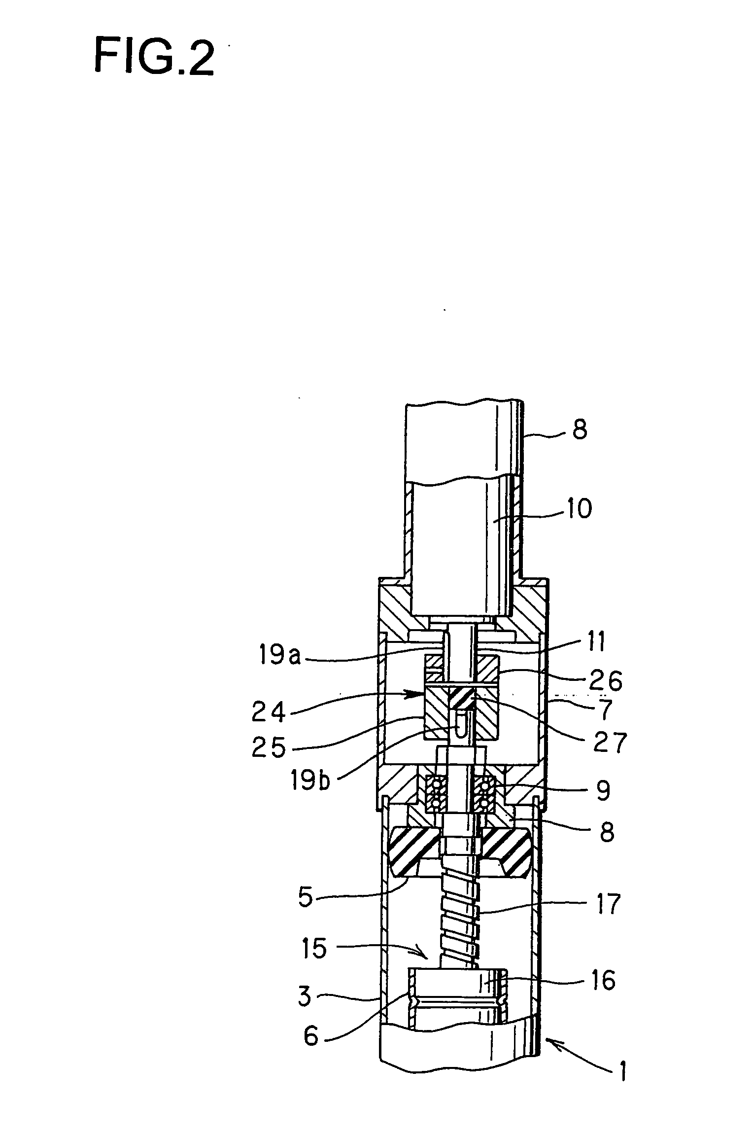
[0083] Next, description of a second embodiment shown in FIG. 2 through FIG. 5 will be given.

[0084] In this embodiment, the constitution is such that a coupling 24 in which an elastic body is arranged is provided as the power transmitting section described above, whereby transmission of rotary torque is delayed, and when rotary torque which a rotary speed of the motor 10 exceeds an allowable limit speed is applied, a vulnerable section is cut and transmission of the rotary torque is stopped.

[0085] In this embodiment, the screw shaft 17 is directly connected with the rotary shaft 11 of the motor 10 by the coupling 24.

[0086] As shown in FIG. 3 through FIG. 5, the coupling 24 is composed of a pair of a drive section 25 and a driven section 26 which are constituted identically with each other and an elastic body 27 which is interposed between the drive section 25 and the driven section 26.

[0087] Because the drive section 25 and the driven section 26 have the identical constitution, o...


PUM


Abstract

An electromagnetic shock absorber according to the present invention has a shock absorber body 1 which makes telescopic motion in response to an input from outside. The shock absorber body 1 comprises a ball screw mechanism 15, which converts the telescopic motion into rotary motion and is composed of a ball nut 16 and a screw shaft 17, and power transmitting sections 13 and 24 having elastic bodies which transmit the rotary motion of the ball screw mechanism 15 to a rotary shaft 11 of a motor 10 while shifting a transmission phase when transmission torque of the rotary motion is changed. The motor 10 generates electromagnetic resistance to oppose against rotations which input into the rotary shaft 11. Thus, vibration or the like which inputs into the shock absorber body 1 from outside is damped by the electromagnetic resistance of the motor 10. Due to the power transmitting sections 13 and 24 which delay a rotary phase, moment of inertia of a rotor of the motor 10 is eased when a shocking load inputs into the shock absorber body 1. Therefore, it is possible to make a vehicle more comfortable to drive when the electromagnetic shock absorber is applied as a shock absorber of the vehicle.

Description

TECHNICAL FIELD [0001] The present invention relates to an electromagnetic shock absorber which converts telescopic motion of a shock absorber body into rotary motion of a motor utilizing a ball screw mechanism and damps vibration utilizing electromagnetic resistance generated by the motor. BACKGROUND ART [0002] A suspension unit for a vehicle in which a hydraulic shock absorber is arranged, in parallel with a suspension spring, between a car body and an axle is well known. [0003] Further, Japanese Patent Laid-Open Publication No. 5-44758A has disclosed a suspension unit in which magnet coils are built in a hydraulic shock absorber. In this suspension unit, coils are attached to a cylinder of the hydraulic shock absorber and magnets are attached to a piston rod, respectively, and an electric current is applied to the coils, thereby generating driving force (electromagnetic force) along the direction of a stroke of the piston rod so as to control the quantity of telescopic motion of ...

Claims


Application Information

Patent Timeline
Patent Type & Authority Applications(United States)
IPC IPC(8): B60G17/015F16F15/03
CPCF16F2232/06F16F15/03
Inventor KONDO, TAKUHIROYAMAGATA, HIDEKISUDA, YOSHIHIRO
Owner KYB CORP
Why Eureka
Try Eureka