Electromagnetic damper

a damper and electromagnetic technology, applied in the direction of shock absorbers, vibration dampers, magnets, etc., can solve the problems of difficult control of damping force, disadvantage in respect of costs, complex structure, etc., and achieve the effect of reducing production costs and being durable and productiv

Inactive Publication Date: 2006-05-11
KONDO TAKUHIRO +1
View PDF5 Cites 17 Cited by
  • Summary
  • Abstract
  • Description
  • Claims
  • Application Information

AI Technical Summary

Benefits of technology

[0028] An advantage of the present invention is to provide an electromagnetic shock absorber capable of excluding as much as possible the influence of the moment of inertia which is hard to control and capable of making vehicles more comfortable to drive.
[0029] An another advantage of the present invention is to provide an electromagnetic shock absorber which is durable and productive and which is capable of reducing the production costs.
[0030] In order to achieve the advantages described above, the electromagnetic shock absorber according to the present invention comprises: a shock absorber body which makes telescopic motion in response to an input from outside; a ball screw mechanism which is arranged at the shock absorber body, converts the telescopic motion into rotary motion, and is composed of a ball nut and a screw shaft; and a motor which is provided coaxially with the shock absorber body and generates electromagnetic resistance to oppose against the rotary motion to be input into a rotary shaft of the motor, and the screw shaft and the rotary shaft of the motor are constituted as one united shaft member.
[0031] The shock absorber body has an external cylinder and an internal cylinder which is slidably inserted into the external cylinder, and the motor is coaxially connected with an upper part of the external cylinder.
[0032] The ball nut of the ball screw mechanism is fixed to an upper part of the internal cylinder. The screw shaft which is united with the rotary shaft of the motor is spirally engaged with the ball nut.
[0033] An intermediate shaft section which connects the screw shaft and the rotary shaft is rotatably supported by an inner surface of the external cylinder through a bearing.

Problems solved by technology

However, in such a suspension unit in which magnet coils are built in a hydraulic shock absorber, a hydraulic pressure, a power source, and the like are required, whereby it is complicated in structure and it is disadvantageous in respect of the costs.
However, it is feared that the following problems may arise if the electromagnetic shock absorber which generates electromagnetic resistance by converting telescopic motion of the shock absorber body into rotary motion of the motor 50 by the ball screw mechanism as described above is actually applied to a vehicle.
Further, referring to the electromagnetic shock absorber's controllability over damping force, although it is possible to freely control the strength of electromagnetic resistance generated by the motor, it is difficult to control the damping force which arises resulting from the moment of inertia of the coupling based on the acceleration of telescopic motion of the above-mentioned shock absorber.
Also, if the rotary shaft and the screw shaft are constituted as separate components and are connected to each other by the coupling, the durability of a joint of the coupling will be liable to be crucial point because rotary force resulting from vibration is always transmitted to the coupling as a shock absorber for a vehicle.
Thus, in order to maintain the reliability, the coupling will be expensive.
Also, in such constitution that the rotary shaft and the screw shaft are connected by the coupling, the number of the components, such as a coupling, is increased and thus assembly line is increased, thereby also affecting productivity and production costs.

Method used


Image

  • Electromagnetic damper
  • Electromagnetic damper
  • Electromagnetic damper

Examples


Embodiment Construction

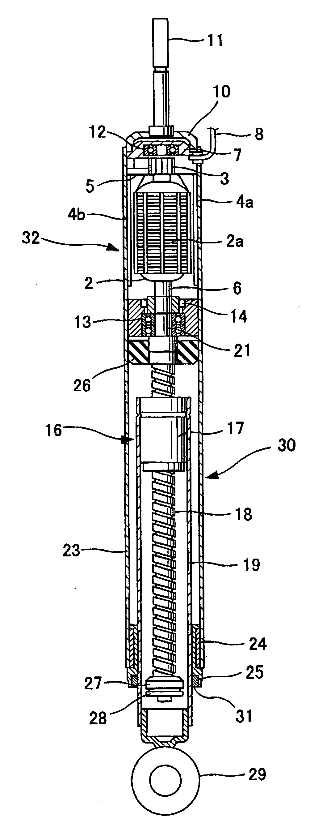
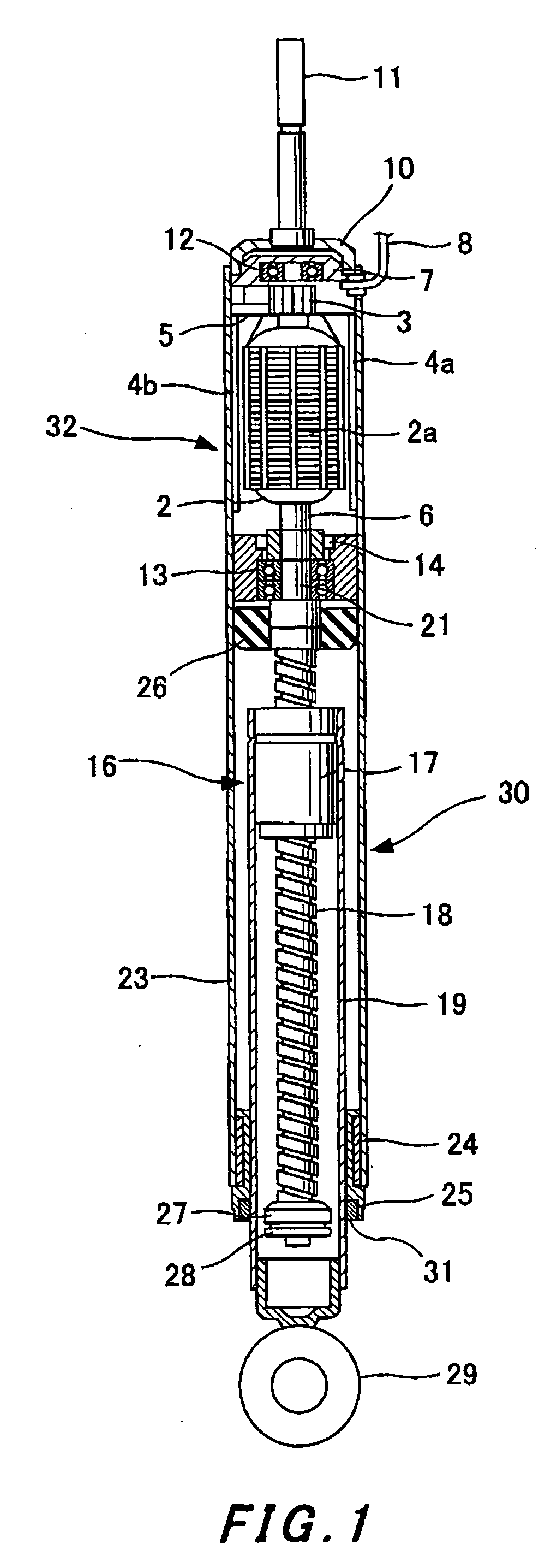
[0040] Description will subsequently be given based on an embodiment shown in FIG. 1

[0041] A shock absorber body 30 which constitutes an electromagnetic shock absorber according to the present invention comprises an external cylinder 23 and an internal cylinder 19 to be coaxially and slidably inserted into the external cylinder 23.

[0042] A motor 32 is arranged above the external cylinder 23, and a screw shaft 18 which constitutes a ball screw mechanism 16 is coaxially arranged in the internal cylinder 19. A ball nut 17 to be spirally engaged with the screw shaft 18 is fixed to an upper part of the internal cylinder 19. When the internal cylinder 19 makes telescopic motion with respect to the external cylinder 23, the screw shaft 18 to be spirally engaged with the ball nut 17 makes rotary motion at the position.

[0043] It is arranged such that a shaft section 6 of the motor 32 is provided on an extension line of the screw shaft 18 as a shaft member united with the screw shaft 18 and...


PUM


Abstract

A shock absorber body 30 which makes telescopic motion in response to an input from outside has a ball screw mechanism 16 which converts the telescopic motion into rotary motion and comprises a ball nut 17 and a screw shaft 18. A motor 32 is provided coaxially with the shock absorber body 30. The motor 32 generates electromagnetic resistance to oppose against the rotary motion which inputs into a rotary shaft 6 of the motor 32. The screw shaft 18 and the rotary shaft 6 are formed as one united shaft member. Damping force which opposes against the telescopic motion of the shock absorber body 30 is generated according to electromagnetic force of the motor 32.

Description

TECHNICAL FIELD [0001] The present invention relates to an electromagnetic shock absorber which converts telescopic motion of a shock absorber body into rotary motion of a motor utilizing a ball screw mechanism and damps vibration utilizing electromagnetic resistance generated by the motor. BACKGROUND ART [0002] A suspension unit for a vehicle in which a hydraulic shock absorber is arranged, in parallel with a suspension spring, between a car body and an axle is widely known. [0003] Further, Japanese Patent Laid-Open Publication No. 5-44758A has disclosed a suspension unit in which magnet coils are built in a part of a hydraulic shock absorber. In this suspension unit, coils are attached to a cylinder of the hydraulic shock absorber and magnets are attached to a piston rod, respectively, and an electric current is applied to the coils, thereby generating driving force (electromagnetic force) along the direction of a stroke of the piston rod so as to control the quantity of telescopi...

Claims


Application Information

Patent Timeline
Patent Type & Authority Applications(United States)
IPC IPC(8): F16F9/34F16F15/03
CPCF16F15/03F16F2232/06F16F6/00F16F7/00
Inventor KONDO, TAKUHIROSUDA, YOSHIHIRO
Owner KONDO TAKUHIRO
Why Eureka
Try Eureka