

Recognition device and method for radical driving state of driver
A technology of aggressive driving and recognition methods, applied in the field of driving behavior recognition, can solve the problems of low utilization rate of vehicle equipment, ignore the utilization of vehicle equipment resources, increase costs, etc., achieve good market promotion value, low device cost, and avoid waste Effect
- Summary
- Abstract
- Description
- Claims
- Application Information
AI Technical Summary
Problems solved by technology
Method used
Image

Examples
Embodiment Construction
[0036] The device and method for identifying a driver's aggressive driving state according to the present invention will be further described in detail below in conjunction with the accompanying drawings and specific embodiments.
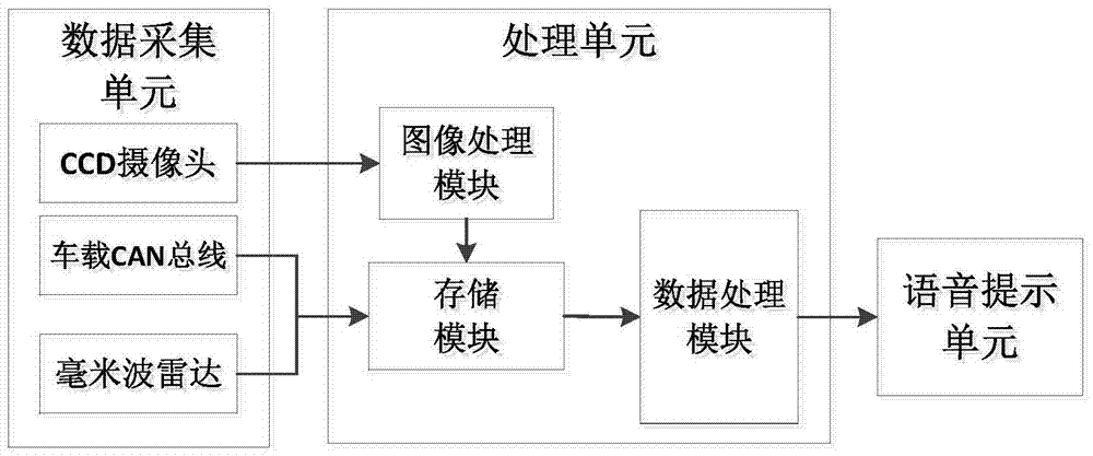
[0037] Such as figure 1 The driver's aggressive driving state recognition device diagram shown includes a data acquisition unit, a processing unit, and a voice prompt unit; the data acquisition unit includes a CCD camera, a vehicle-mounted CAN bus, and a millimeter wave radar; the processing unit includes an image processing module, a storage module, and a data processing unit. Processing module; voice prompt unit adopts ISD1730 voice chip.
[0038] The CCD camera collects the lane image of the target vehicle, and sends it to the image processing module; the image processing module extracts the lane centerline position through preprocessing, boundary detection, Hough transformation, and feature extraction steps, and stores it in the In the storage mo...
PUM
 Abstract
Description
Claims
Application Information