Concentrated cotton removal device of roving frame

A technology of roving frames and cotton troughs, which is applied in the direction of textiles and papermaking, etc., which can solve the problems of large labor and time consumption, accumulation of waste flowers, and poor removal of waste flowers, so as to save labor, improve efficiency, and achieve good cotton removal effect Effect

Inactive Publication Date: 2016-03-30
WUXI HONGYUAN ELECTROMECHANICAL TECH
View PDF11 Cites 10 Cited by
  • Summary
  • Abstract
  • Description
  • Claims
  • Application Information

AI Technical Summary

Problems solved by technology

In the prior art, waste flowers will accumulate on the inner wall of the cotton collection tank and the inner side of the endless belt, and the effect of removing waste flowers is not good. At the same time, manual cleaning of waste cotton will consume a lot of labor and time

Method used


Image

  • Concentrated cotton removal device of roving frame
  • Concentrated cotton removal device of roving frame
  • Concentrated cotton removal device of roving frame

Examples


Embodiment

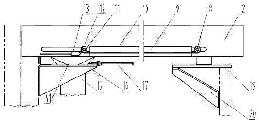
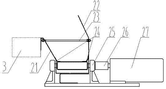
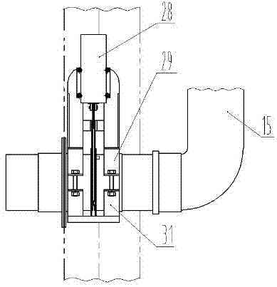
[0021] Example : A centralized cotton removal device for a roving frame, such as figure 1 As shown, it includes a cotton removal tank 2, an endless belt 10, a cleaning scraper 12, a waste flower discharge port 41 and an air duct 15. Cotton removal slot 2 extends along the horizontal direction, from figure 2 It can be seen from the side view that the cotton removal tank 2 is formed by extending upwards from a U-shaped structure at the bottom to form two front and rear side walls 21, 22 inclined in the same direction, wherein the front side wall is fixed on the vehicle surface 3, The rear side wall 22 is higher than the front side wall 21, and the top end of the front side wall 21 is connected to the bottom end of the rear side wall 22 by pins 23, and the rear side wall 22 located above is inclined inwardly so that waste flowers can be blocked in the cotton removal groove 2 within. In the cotton removal tank 2, an endless belt 10 is arranged, and the endless belt 10 is slee...


PUM


Abstract

The invention discloses a concentrated cotton removal device of a roving frame. The concentrated cotton removal device comprises a cotton removal groove, an annular belt arranged in the cotton removal groove, a cleaning scraper located at one end of the annular belt, a waste cotton discharge port formed in the tail end of the cotton removal groove and located below the cleaning scraper, and an air pipe with one end connected with the waste cotton discharge port and the other end connected with a draught fan. The edge of the cleaning scraper makes contact with the surface of the annular belt to conduct scraping. Waste cotton is conveyed through the annular belt, waste cotton on the belt is scraped into the air pipe through the cleaning scraper at the tail end of the cotton removal groove, waste cotton in the air pipe is removed through wind power of the draught fan instead of manual operation, the structure is simple, the cotton removal effect is good, labor is saved, and efficiency is improved.

Description

technical field [0001] The invention relates to the field of textile machinery, in particular to a roving frame. Background technique [0002] During the working process of the roving frame, waste flowers will be produced. Under the action of the circuit blowing and suction system, part of it enters the suction pipe, and is discharged through the dust discharge pipe under the action of the fan; the other part enters the cotton collecting device behind the roving frame body, and the cleaning scraper is set on the rotary endless belt. On the top, the ring-shaped belt drives the scraper to scrape from one end of the cotton collection tank to the other end, scraping the waste flowers to the waste flower exit, and then falling into the cotton collection box, and the waste cotton is cleaned manually at regular intervals. In the prior art, waste cotton will accumulate on the inner wall of the cotton collection tank and the inner side of the endless belt, and the effect of removing...

Claims


Application Information

Patent Timeline
Patent Type & Authority Applications(China)
IPC IPC(8): D01H11/00
CPCD01H11/006
Inventor 沈丽芳丁坚王秀丽
Owner WUXI HONGYUAN ELECTROMECHANICAL TECH
Why Eureka
Try Eureka