Automobile fan impeller

A fan impeller and fan blade technology, applied in the field of auto parts, can solve problems such as interfering with airflow discharge and reducing fan cooling efficiency

Inactive Publication Date: 2016-03-30
WUHU DEXIN AUTO PARTS
View PDF4 Cites 5 Cited by
  • Summary
  • Abstract
  • Description
  • Claims
  • Application Information

AI Technical Summary

Problems solved by technology

When the fan generates airflow to blow on the electronic components, the turbulence generated near the hub will seriously interfere with the overall airflow and greatly reduce the heat dissipation performance of the fan

Method used


Image

  • Automobile fan impeller

Examples


Embodiment Construction

[0019] Specific embodiments of the present invention will be described in detail below in conjunction with the accompanying drawings. It should be understood that the specific embodiments described here are only used to illustrate and explain the present invention, and are not intended to limit the present invention.

[0020] In the present invention, unless stated otherwise, the orientation words included in the term, such as "outward", only represent the orientation of the term in the normal use state, or the common name understood by those skilled in the art, rather than should be considered a limitation of the term.

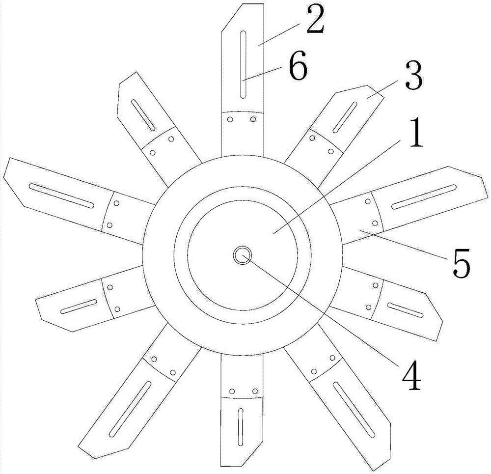
[0021] see figure 1 , the present invention provides an automobile fan impeller, which comprises a hub 1, a first fan blade 2 and a second fan blade 3 arranged along the circumferential direction of the hub 1; one end of the first fan blade 2 is fixedly connected to the hub 1 and the other end extends outward in the radial direction; one end of the second b...


PUM


Abstract

The invention discloses an automobile fan impeller. The automobile fan impeller comprises a hub (1), first fan blades (2) and second fan blades (3). The first fan blades (2) and the second fan blades (3) are arranged in the circumferential direction of the hub (1). One ends of the first fan blades (2) are fixedly connected to the outer wall of the hub (1), and the other ends of the first fan blades (2) extend outwards in the radial direction; one ends of the second fan blades (3) are fixedly connected to the outer wall of the hub (1), and the other ends of the second fan blades (3) extend outwards in the radial direction; the length of the first fan blades (2) is 1.5 to 2 times that of the second fan blades (3); and the first fan blades (2) and the second fan blades (3) are arranged in a staggered manner. According to the automobile fan impeller, turbulence generated in the position close to the hub can be prevented from disturbing emission of the whole air flow, and the heat dissipation efficiency of a fan can be enhanced.

Description

technical field [0001] The invention relates to the field of automobile parts, in particular to an automobile fan impeller. Background technique [0002] Existing fans often include a fan frame, an impeller and a motor accommodated inside the fan frame, wherein the impeller is composed of a hub and a plurality of fan blades, and the plurality of fan blades have the same length and the same radius of rotation. However, in the existing fan, since the plurality of fan blades take the hub as the axis and extend outward along the radial direction of the hub, when the hub drives the plurality of fan blades to rotate, each fan blade is adjacent to one end of the hub. The axial velocity of the fan is bound to be smaller than the axial velocity of the end away from the hub, which will cause the uneven distribution of the axial velocity of the air entering the fan, resulting in the air volume generated by the end of the fan blade adjacent to the hub is smaller than the air volume gene...

Claims


Application Information

Patent Timeline
Patent Type & Authority Applications(China)
IPC IPC(8): F04D29/32F04D29/34F04D29/38
CPCF04D29/327F04D29/34F04D29/388
Inventor 王飞张传喜
Owner WUHU DEXIN AUTO PARTS
Why Eureka
Try Eureka