Vacuum glass air exhaust method and air exhaust device

A technology of vacuum glass and air extraction device, which is applied in the direction of pump device, liquid variable capacity machine, variable capacity pump components, etc., which can solve the problems of reduced quality of vacuum glass products, affecting the efficiency of pumping, shortening the service life, etc., to achieve Guaranteed processing quality and service life, wide application range, and the effect of avoiding damage

Active Publication Date: 2019-10-15
洛阳兰迪真空玻璃科技有限公司
View PDF6 Cites 1 Cited by
  • Summary
  • Abstract
  • Description
  • Claims
  • Application Information

AI Technical Summary

Problems solved by technology

Especially when the size of the vacuum glass is large, if the pumping speed of the pumping device is fast, the pressure in the vacuum chamber will also drop rapidly, which will cause the instantaneous pressure difference inside and outside the vacuum glass to become very large. At this time, due to the vacuum glass If the external pressure is lower than its internal pressure, the inner cavity 1205 of the vacuum glass will expand, and a tearing force will be formed in the sealing structure 1203 during the expansion process, resulting in a decrease in the quality of the vacuum glass product and shortening the service life
If it is replaced with a smaller pipeline and pump unit, although it can better meet the demand in the early stage of the pumping stage and ensure that the pressure difference between the inside and outside of the vacuum glass is in an appropriate range, when the overall pressure drops to a certain value, it needs to continue to drop quickly to a certain value. When the target value is exceeded, the defect of insufficient pumping capacity will be exposed, which will greatly affect the pumping efficiency

Method used


Image

  • Vacuum glass air exhaust method and air exhaust device
  • Vacuum glass air exhaust method and air exhaust device
  • Vacuum glass air exhaust method and air exhaust device

Examples


Embodiment Construction

[0039] The technical solution of the present invention will be further described through specific implementation manners below in conjunction with the accompanying drawings.

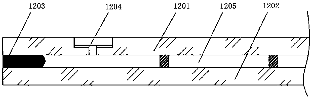
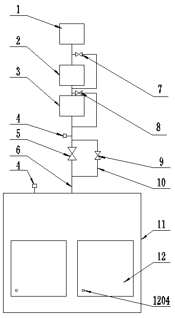
[0040] As shown in the figure, a vacuum glass suction device includes a main suction pipeline 6 and a branch line suction pipeline 10 arranged on the main suction pipeline 6. The main suction pipeline 6 is connected to the suction pump, and the suction pump selects the rotary vane Pump 1, Roots pump group 2 and molecular pump 3, the rotary vane pump 1 is connected to the main suction pipeline 6 through the main pipe, the Roots pump group 2 and molecular pump 3 are connected to the main pipe, and on the main pipe side A first bypass pipe and a second bypass pipe are provided. The first bypass pipe is provided with a valve Ⅱ7, which is connected in parallel with the Roots pump unit 2. The second bypass pipe is provided with a valve Ⅲ8, a valve Ⅲ8 and The molecular pumps 3 are connected in parallel; the mai...


PUM

PropertyMeasurementUnit
diameteraaaaaaaaaa
diameteraaaaaaaaaa

Abstract

The invention relates to vacuum glass air exhaust method and device. The device is provided with a main air exhaust pipeline, a branch air exhaust pipeline and a relevant air exhaust pump. Through themethod characterized by firstly using the branch air exhaust pipeline for exhausting air at low speed and then using the main air exhaust pipeline for quickly exhausting air, a pressure difference between an inner chamber of vacuum glass and a vacuum chamber caused by an air exhaust efficiency difference inside and outside the vacuum glass in the vacuum extraction process in the prior art is effectively avoided, the damage on a sealing structure due to the pressure difference in the vacuum extraction process is further avoided, and the processing quality and the service life of the vacuum glass are ensured.

Description

technical field [0001] The invention relates to the technical field of vacuum glass, in particular to a vacuum glass pumping method and a pumping device. Background technique [0002] Such as figure 1 As shown, the vacuum glass in the prior art generally includes: a first glass plate 1201, a second glass plate 1202, a sealing structure 1203 and an exhaust hole 1204 arranged on one of the glass plates; wherein the first glass plate 1201, the second glass plate The glass plate 1202 and the sealing structure 1203 enclose the inner cavity 1205 of the vacuum glass. In order to realize the continuous production of the above-mentioned vacuum glass, the vacuum glass needs to be processed in a vacuum chamber, and in the production process, it is necessary to evacuate the vacuum chamber used for processing the vacuum glass, and at the same time, the inner cavity of the vacuum glass that needs to be ventilated and sealed Vacuum. Afterwards, the vacuum glass assembly will be subjecte...

Claims


Application Information

Patent Timeline
Patent Type & Authority Applications(China)
IPC IPC(8): F04B41/06F04B39/12F04B39/10F04B37/14C03C27/06
CPCC03C27/06F04B37/14F04B39/10F04B39/123F04B41/06
Inventor 赵雁庞世涛李金玉
Owner 洛阳兰迪真空玻璃科技有限公司
Why Eureka
Try Eureka