Novel aviation kerosene coalescence separator

A technology of coalescing separator and jet fuel, which is applied in the field of separators and new jet fuel coalescing separators. Reduced service life and other issues, to avoid abnormal pressure difference of coalescer separator, reduce manual operation, and achieve long-term stable operation

Pending Publication Date: 2021-08-03
浙江石油化工有限公司
View PDF0 Cites 1 Cited by
  • Summary
  • Abstract
  • Description
  • Claims
  • Application Information

AI Technical Summary

Problems solved by technology

The inlet and outlet of the coalescer are usually set at the lower part of the cylinder of the coalescer. During the actual operation, the pipeline is purged to replace the residual N2 and the trace amount of H dissolved in the oil during the hydrogenation process. Gases such as 2, CH4, which will escape in the jet fuel coalescer and accumulate at the top of the jet coal coalescer, when the accumulated gas is sufficient When it is too large, the top of the filter element will be exposed to the gas, resulting in a decrease in the total effective filtration area of ​​the coalescing separator and an abnormal pressure difference of the coalescing separator, which will easily cause damage to the filter element and reduce the service life of the coalescing separator
In order to prevent the above problems, it is necessary to manually open the hand valve on the top of the coalescence separator to exhaust gas to prevent a large amount of gas accumulation. Manual exhaust will produce a certain amount of volatile organic compounds and cause air pollution. At the same time, there are certain risks such as leakage and fire.

Method used


Image

  • Novel aviation kerosene coalescence separator

Examples


Embodiment Construction

[0016] The present invention is further explained below, but the present invention is not limited to the following examples.

[0017] In response to problems in the prior art, a combined coal aggregation separator that can be monitored in real time and automatically exhaust gas can reduce a large number of artificial work, effectively monitor gas aggregation in real - time and achieve automatic exhaust, Avoiding the differential differences and corruption of the coalescery and the filtering damage, there is a big practical significance.

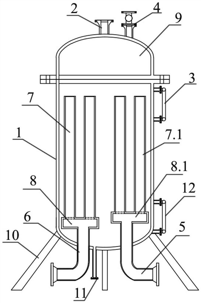
[0018] like figure 1 A specific embodiment of a new type of aircraft coal coalescery separator is shown. This embodiment includes a navigation coal coal coalescery, including a cylindrical body 1, and the upper end of the cylinder 1 is provided with a safety valve interface 2, an automatic row. The air valve 4, the automatic exhaust valve 4 is connected to the torch system by a flange, and the lower end of the cylinder 1 is connected to the inlet...


PUM


Abstract

The invention discloses a novel aviation kerosene coalescence separator which comprises a barrel, a safety valve connector and an automatic exhaust valve are arranged at the upper end of the barrel, the automatic exhaust valve is connected into a torch system, the lower end of the barrel is connected with an inlet pipe and an outlet pipe, and a coalescence filter element, a separation filter element, a coalescence filter element tray and a separation filter element tray are arranged in the barrel. The coalescence filter element is connected to the coalescence filter element tray, the separation filter element is connected to the separation filter element tray, an opening used for being connected with the inlet pipe is formed in the lower portion of the coalescence filter element tray, and an opening used for being connected with the outlet pipe is formed in the lower portion of the separation filter element tray. The bottom of the barrel is further connected with a liquid cutting pipeline. The upper end and lower end of the outer surface of the barrel are connected with a first double-flange liquid level meter and a second double-flange liquid level meter respectively. By means of the coalescence separator, manual operation can be greatly reduced, long-term stable operation of the coalescence separator is achieved, abnormal pressure difference of the coalescence separator and damage to a filter element caused by gas gathering inside the coalescence separator are avoided, and long-term stable operation of the device is kept.

Description

Technical field [0001] The present invention relates to a separator, more specifically, involving a new type of aerobic coalescery separator, belonging to the field of petrochemical. Background technique [0002] The micro-dissolved water dissolved in production and storage during production, if it is not removed, this part of water may generate crystallization due to the low ambient temperature of the engine fuel system due to the aircraft flight, resulting in filtration. Blocked the oil supply interruption, causing serious air accidents, homework production equipment, tank area, etc. need to set the filter, coalescery separator, remove moisture in the aerospace, to ensure aviation safety . The coalescery separator is inward, and the exit is usually provided on the lower portion of the coalescerator cylinder body, during the actual operation, the pipe is purged with the residual N 2 , Slightly hinding of oil in oil in hydrogenation 2 CH 4 The gas is escaping in the aerobic coal ...

Claims


Application Information

Patent Timeline
Patent Type & Authority Applications(China)
IPC IPC(8): B01D17/02
CPCB01D17/02
Inventor 汪武义崇鹏郭建伟李明张杰
Owner 浙江石油化工有限公司
Why Eureka
Try Eureka