Optical field molten salt flow and defocus adjustment coordination control device for trough photothermal power station

A technology of flow regulation and coordinated control, which is applied in the direction of heating devices, solar thermal devices, solar thermal power generation, etc., can solve problems such as unresolved background technical problems, achieve high operating efficiency, high-efficiency long-term stable operation, and reduce system costs. The effect of energy loss

Active Publication Date: 2017-05-31
中国东方电气集团有限公司
View PDF10 Cites 0 Cited by
  • Summary
  • Abstract
  • Description
  • Claims
  • Application Information

AI Technical Summary

Problems solved by technology

[0007] In summary, the above-mentioned patents do not solve the technical problems mentioned in the background technology

Method used


Image

  • Optical field molten salt flow and defocus adjustment coordination control device for trough photothermal power station
  • Optical field molten salt flow and defocus adjustment coordination control device for trough photothermal power station
  • Optical field molten salt flow and defocus adjustment coordination control device for trough photothermal power station

Examples


Embodiment 1

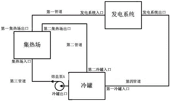
[0037] The trough photothermal power station includes a cold tank, a heat collecting field and a power generation system. The cold tank includes a first cold tank inlet, a second cold tank inlet and a cold tank outlet. The heat collecting field includes a first heat collecting field outlet , the second heat collection field outlet and the heat collection field inlet, the power generation system includes a power generation system inlet and a power generation system outlet; the cold tank outlet is connected to the heat collection field inlet through a third pipeline, and the cold tank outlet also A molten salt pump A is installed; the outlet of the first heat collection field is connected to the inlet of the power generation system through the first pipeline, the outlet of the power generation system is connected to the inlet of the first cold tank through the fourth pipeline, and the second The heat collecting field outlet is connected to the second cold tank inlet through a sec...

Embodiment 2

[0043] The trough photothermal power station includes a cold tank, a heat collecting field and a power generation system. The cold tank includes a first cold tank inlet, a second cold tank inlet and a cold tank outlet. The heat collecting field includes a first heat collecting field outlet , the second heat collection field outlet and the heat collection field inlet, the power generation system includes a power generation system inlet and a power generation system outlet; the cold tank outlet is connected to the heat collection field inlet through a third pipeline, and the cold tank outlet also A molten salt pump A is installed; the outlet of the first heat collection field is connected to the inlet of the power generation system through the first pipeline, the outlet of the power generation system is connected to the inlet of the first cold tank through the fourth pipeline, and the second The heat collecting field outlet is connected to the second cold tank inlet through a sec...

Embodiment 3

[0055] The trough photothermal power station includes a cold tank, a heat collecting field and a power generation system. The cold tank includes a first cold tank inlet, a second cold tank inlet and a cold tank outlet. The heat collecting field includes a first heat collecting field outlet , the second heat collection field outlet and the heat collection field inlet, the power generation system includes a power generation system inlet and a power generation system outlet; the cold tank outlet is connected to the heat collection field inlet through a third pipeline, and the cold tank outlet also A molten salt pump A is installed; the outlet of the first heat collection field is connected to the inlet of the power generation system through the first pipeline, the outlet of the power generation system is connected to the inlet of the first cold tank through the fourth pipeline, and the second The heat collecting field outlet is connected to the second cold tank inlet through a sec...


PUM


Abstract

The invention relates to the technical field of solar groove type photo-thermal power generation, in particular to a coordinated control device for light field fused salt flow adjustment and defocusing adjustment of a groove type photo-thermal power station. The coordinated control device comprises a heat collecting field flow adjustment control unit, a heat collecting field defocusing adjustment control unit and a central coordinated control unit, wherein the heat collecting field flow adjustment control unit and the heat collecting field defocusing adjustment control unit are connected through a communication network and are connected with the central coordinated control unit. The heat collecting field flow adjustment control unit is used for controlling the flow of a cold tank outlet according to commands of the central coordinated control unit. By means of the coordinated control device, a photo-thermal power generation system is made to guarantee that fused salt stably flows without condensation when solar illumination intensity is poor according to solar illumination intensity differences in time, meanwhile, the temperature of the fused salt is controlled not to exceed the standard when the solar illumination intensity is too high, and therefore the photo-thermal power generation system can stably operate with high efficiency for a long time under complex and diversified weather conditions.

Description

technical field [0001] The invention relates to the technical field of solar trough photothermal power generation, in particular to a coordinated control device for adjusting and controlling molten salt flow and defocusing in a trough photothermal power station. Background technique [0002] Solar thermal power generation is a clean energy method that can be concentrated for large-scale power generation. The trough system is currently among the solar thermal power generation methods, with the highest degree of technical maturity and commercialization verification. The heat source required for solar thermal power generation all comes from sunlight, and the intensity of sunlight varies greatly at different time points in a day. Due to the long process of starting and stopping the solar thermal power generation system, the steps are cumbersome and the cost is high. [0003] When the light conditions are moderate, it is necessary to control the outlet temperature of the molten ...

Claims


Application Information

Patent Timeline
Patent Type & Authority Patents(China)
IPC IPC(8): F24J2/40
CPCY02E10/40
Inventor 周宏林刘征宇冯玲吴建东
Owner 中国东方电气集团有限公司
Why Eureka
Try Eureka