Method for error correction in position measuring devices

A technology for correcting errors and measuring devices, which is applied in the field of correcting errors, can solve the problems that a storage unit cannot be corrected with measured values, and cannot be used for measuring work, etc., and achieves the effects of reducing transmission duration, cost, and volume.

Active Publication Date: 2016-03-30
DR JOHANNES HEIDENHAIN GMBH
View PDF9 Cites 4 Cited by
  • Summary
  • Abstract
  • Description
  • Claims
  • Application Information

AI Technical Summary

Problems solved by technology

During this time, the memory cell with the correction table cannot be used for the correction of the measured value or for measuring work

Method used


Image

  • Method for error correction in position measuring devices
  • Method for error correction in position measuring devices
  • Method for error correction in position measuring devices

Examples


no. 1 example

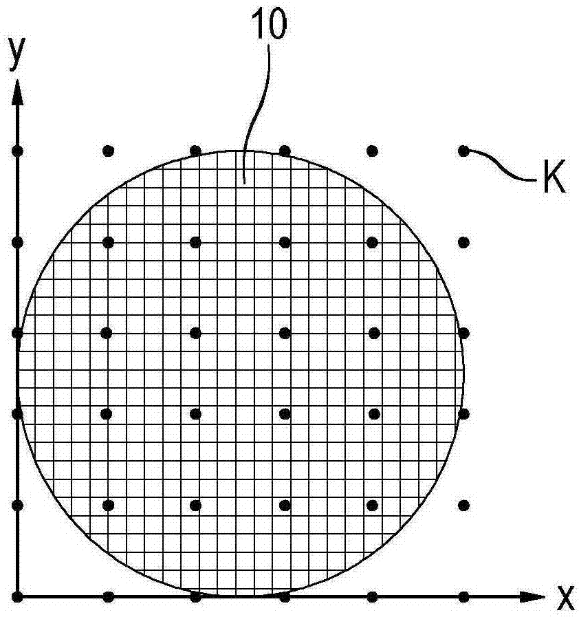
[0053] According to the prior art, the storage of the correction values ​​takes place in a two-dimensional matrix, wherein the matrix input values ​​are equal to the correction values ​​at specific xy positions of measuring standard 10 . The corresponding matrices are stored, for example, in series in a suitable memory location, so that in the case of a large number of correction points K with a large character width, the problems mentioned at the outset result due to the resulting large data volume. The advantage of storing correction points K in a matrix lies in the simple and rapid processing in signal processing unit 40 . In order for all correction points K to be able to be stored in the matrix, the matrices must be dimensioned such that they form the circumscribed rectangle of all relevant correction points K'. If measuring standard 10 now has a non-rectangular configuration or scanning unit 20 does not traverse the entire measuring standard 10 in a rectangular range dur...


PUM


Abstract

The present invention relates to a method for error correction in position measuring devices with material measures, which are scanned by at least one scanning unit, wherein for a defined number of correction points on the scale embodiment respectively correction values are kept, which recovered from a place before the measuring mode calibration and in measuring mode correction the detected position values are used. The correction values obtained during the calibration are compressed for the measurement operation.

Description

technical field [0001] The invention relates to a method for correcting errors in a position measuring device. Background technique [0002] Known position measuring devices generally include one or more gauges and one or more scanning units that are movable relative to the gauges. A linear scale or a crossed scale is usually designed as a measuring instrument here with a grid graduation attached thereto. The desired position of the scanning unit relative to the measuring standard is determined by scanning the grid scale with the scanning unit; magnetic, inductive and capacitive scanning principles are also known here in addition to optical scanning principles. In addition to other properties of the position-measuring device, the accuracy with which the position can be measured depends largely on the accuracy of the grid scale on the measuring standard. For general measuring applications, in the case of optical scanning, corresponding grid graduations can be produced with ...

Claims


Application Information

Patent Timeline
Patent Type & Authority Applications(China)
IPC IPC(8): G01B21/00
CPCG01D18/008G01D18/00
Inventor 约尔格·德雷谢尔乌尔里希·比希尔迈耶
Owner DR JOHANNES HEIDENHAIN GMBH
Why Eureka
Try Eureka